Vents and Holes
Openings
tab in model data
Vents
DesignBuilder vents are used for modelling airflow through openings
and are added to the model by navigating to the appropriate surface and
checking the Vents fitted option. This
adds a single vent under each of the windows (if the vent spacing is the
same as the window spacing). Alternatively, for more control over the
placement position of the vents, you can go to surface level and draw
the vents using the Draw vent command. On
surfaces where custom openings have been defined, any changes to vent
layout model data on the Opening
tab is ignored.
Note: if you
have drawn custom vents at the surface level then these will be used even
if the Vents fitted checkbox is not checked.
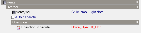
The Vents fitted checkbox only controls
the automatic generation of vents, not their use in the calculations.
The properties of the vent are defined by the selection of the vent type:
Holes
Holes are modelled in a similar way to vents
with some exceptions:
- Holes must be drawn at surface level
- Airflow through holes is uncontrolled, i.e. the
airflow path is active all the time.
- Drawing holes can be used as a way to merge
two zones when the Merge zones connected
by holes Model option is set.
- Holes are used internally with DesignBuilder to
model the heat transfer and airflow through Virtual
partitions.
- Discharge coefficient of 0.65 is used whereas
with vents the vent component defines the discharge coefficient.
Vent modelling
Calculated Natural Ventilation (Simulations
only)
Each vent is modelled using:
- An EnergyPlus 'Door'. The heat conduction through
the vent 'door' component is displayed in results as Internal
Natural vent and External Natural vent.
- An EnergyPlus 'AIRFLOWNETWORK:MULTIZONE:COMPONENT
DETAILED OPENING' and other associated AIRFLOW components, providing a
controllable flow path. You can define Vent
operation.
Scheduled Natural Ventilation (and Design
Calculations)
Each vent is modelled using:
- An EnergyPlus 'Door'. The heat conduction through
the vent 'door' component is displayed in results as Internal
Natural vent and External Natural vent.
- Internal vents have an EnergyPlus 'Mixing' object
using parameters
set in the Model options dialog.
External vents .
Hole modelling
Calculated Natural Ventilation (Simulations
only)
Each hole is modelled using a sub-surface and an airflow connection:
- Sub-surface:
- If using 1-Minimum
shadowing or 2-Full exterior solar
distribution the hole is represented using an EnergyPlus 'Door'. In this case the heat conduction through the
vent 'Door' component is displayed in results as Internal Natural vent
and External Natural vent.
- If the 3-Full
interior and exterior solar distribution Model option is set then
the hole is modelled using a 'perfectly clear' window which transmits
solar radiation and visible light.
- EnergyPlus 'AIRFLOWNETWORK:MULTIZONE:COMPONENT
DETAILED OPENING' and other associated AIRFLOW components, providing a
controllable flow path. You can define Vent
operation.
Scheduled Natural Ventilation (and Design
Calcs)
Each hole is modelled using a sub-surface and a 'mixing' flow:
- Sub-surface:
- If using 1-Minimum
shadowing or 2-Full exterior solar
distribution the hole is represented using an EnergyPlus 'Door'. In this case the heat conduction through the
vent 'Door' component is displayed in results as Internal Natural vent
and External Natural vent.
- If the 3-Full
interior and exterior solar distribution Model option is set then
the hole is modelled using a 'perfectly clear' window which transmits
solar radiation and visible light.
- Internal vents have an EnergyPlus 'Mixing' object
using parameters
set in the Model options dialog.
External vents.