![]() ZoneHVAC:FourPipeFanCoil
ZoneHVAC:FourPipeFanCoil
Used in:
HVAC Zones
|
|
|
Used in:
HVAC Zones |
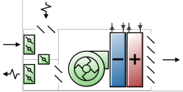
The EnergyPlus Fan coil unit (FCU) is an in-room forced-convection hydronic unit. Typically these units are small (200 – 1200 cfm) and self-contained. They are mostly used in exterior zones, usually in hotels, apartments, or offices. They may be connected to ducted outside air, or have a direct outside air vent, but they do not have outside air economizers.
The heating or cooling output of the unit ventilator is controlled by varying the air flow rate, the water flow rate, or both. Air flow rate can be controlled by cycling the fan on/off or with a variable speed fan drive. The most common setup is a two or three speed fan with the speed selected by hand. The fan then cycles on/off to control heating / cooling output. The controls are often a wall mounted thermostat with hand selection of heating/cooling and fan speed (off/low/medium/high). These controls may also be mounted on the unit.
 See the Chilled Water Loop and FCU Tutorial
Fan coil units are objects made up of other components. Each FCU consists all of these fixed components:
Default settings are assigned to these components at the point the FCU is created and these can be overridden by editing the individual component properties.
The fan coil unit is connected to a hot water loop (demand side) through its hot water coil and to a chilled water loop (demand side) through its cooling coil.
An outdoor air mixer is one of the components of the FCU. See above under Outdoor Air Supply for details of data entry.
A fan component is one of the components of a fan coil unit. See above under Fan type for details of fan types that are used.
Like many HVAC terms, “fan coil unit” is used rather loosely. Sometimes it is used for terminal units that would be better described as powered induction units. Carrier and others use the term for the room side of refrigerant-based split systems.
Real world fan coil units can be 4-pipe or 2-pipe. For 4-pipe units there are 2 supply pipes and 2 return pipes. For 2-pipe units there is a single supply pipe and a single return pipe. Change-over systems enable you to switch the supply between hot and chilled water depending on the season. DesignBuilder provides only a 4-pipe unit, but the 4-pipe model can be used to model 2-pipe units simply by using the heating and cooling coil availability schedules to make sure that either hot or chilled water is exclusively available.
Units with outside air economizers are marketed (in the United States) as unit ventilators. Unit ventilators are typically bigger than fan coils and are widely used in classrooms or other applications where ventilation is a priority. If a zonal unit with an outside economizer is required, ZoneHVAC:UnitVentilator should be used (not yet implemented in DesignBuilder Detailed HVAC).
A unique system-assigned name for an instance of a Fan Coil unit. Any reference to this Fan Coil unit by another object will use this name.
Schedule that defines whether the fan coil unit can run during a given time period. A schedule value greater than 0 (usually 1 is used) indicates that the fan coil unit can be on during a given time period. A value less than or equal to 0 (usually 0 is used) denotes that the fan coil unit is off.
This input denotes how the unit’s output is controlled in order to meet zone heating or cooling requirement. The choices are
This is the ratio of the low speed supply air flow rate to the maximum supply air flow rate. Its value should be less than Medium speed supply air flow ratio below. The default value is 0.33.
This data is only required if the capacity control method selected is 2-Cycling fan.
This is the ratio of the medium speed supply air flow rate to the maximum supply air flow rate. Its value should be greater than the Low speed supply air flow ratio above, but less than 1. The default value is 0.66.
This data is only required if the capacity control method selected is 2-Cycling fan.
When the Capacity control method is set to 1-Constant fan variable flow you can select the type of fan. Choose from:
For the other types of Capacity control method the fan type is fixed internally based on the method. For 2-Cycling fan, an On/off fan is used and for 3-Variable fan variable flow or 4-Variable fan constant flow a Variable volume fan will be used.
The maximum volumetric airflow rate (m3/sec or ft3/min) through the fan coil unit. This is also the design, rated airflow rate of the unit.
Check this option if the fan coil unit includes an outdoor air supply.
If the fan coil unit uses outdoor air, this data specifies the outdoor air volumetric flow rate (m3/sec or ft3/min). This flow rate should be less than or equal to the maximum airflow rate.
A cooling coil is another component of the fan coil unit. Only the standard water cooling coil type is available.
The maximum cold water volumetric flow rate (m3/sec or gal/min) through the fan coil unit’s cooling coil.
The minimum cold water volumetric flow rate (m3/sec or gal/min) through the fan coil unit’s cooling coil.
Heating coil component also make up part of the fan coil unit. Only the standard water heating coil type can be used.
The maximum hot water volumetric flow rate (m3/sec or gal/min) through the fan coil unit’s heating coil.
The minimum hot water volumetric flow rate (m3/sec or gal/min) through the fan coil unit’s heating coil.
The convergence tolerance for the control of the unit cooling output can be defined. The unit is controlled by matching the unit output to the zone demand. For units with water coils, the model must be numerically inverted to obtain a specified output. The cooling convergence tolerance is the error tolerance used to terminate the numerical inversion procedure. Basically this is the fraction:
(Qfan coil out - Qzone load) / Qzone load <= Cooling Convergence Tolerance
The convergence tolerance for the control of the unit heating output can be defined. The unit is controlled by matching the unit output to the zone demand. For units with water coils, the model must be numerically inverted to obtain a specified output. The heating convergence tolerance is the error tolerance used to terminate the numerical inversion procedure. Basically this is the fraction:
(Qfan coil out - Qzone load) / Qzone load <= Heating Convergence Tolerance
HVAC,Average,Fan Coil Heating Rate[W]
HVAC,Sum,Fan Coil Heating Energy[J]
HVAC,Average,Fan Coil Total Cooling Rate[W]
HVAC,Sum,Fan Coil Total Cooling Energy[J]
HVAC,Average,Fan Coil Sensible Cooling Rate[W]
HVAC,Sum,Fan Coil Sensible Cooling Energy[J]
HVAC,Average,Fan Coil Electric Power[W]
HVAC,Sum,Fan Coil Electric Consumption[J]
HVAC,Average,Fraction Of Timestep Fancoil is ON []
HVAC,Average,Fan Speed []
This field reports the dry air heating addition rate of the fan coil unit to the zone it is serving in Watts. This is determined by outlet and zone air conditions and the mass flow rate through the unit.
This field is the dry air heat addition of the fan coil unit to the zone it is serving in Joules over the timestep being reported. This is determined by outlet and zone air conditions, the mass flow rate through the unit, and the timestep.
This field is the total (sensible and latent) heat extraction rate of the fan coil unit from the zone it is serving in Watts. This is determined by the outlet and zone conditions and the mass flow rate through the unit.
This field is the total (sensible and latent) heat extraction of the fan coil unit from the zone it is serving in Joules over the timestep being reported. This is determined by outlet and zone air conditions, the mass flow rate through the unit, and the timestep.
This field reports the dry air sensible heat extraction rate of the fan coil unit from the zone it is serving in Watts. This is determined by the outlet and zone conditions and the mass flow rate through the unit.
This field is the dry air sensible heat extraction of the fan coil unit from the zone it is serving in Joules over the timestep being reported. This is determined by the outlet and zone conditions, the mass flow rate through the unit, and the timestep.
This field reports the electricity consumption rate of the fan coil unit in Watts.
This field is the electricity consumption of the fan coil unit in Joules over the timestep being reported.
This field is the fraction of the system timestep the fan coil unit is running for the CyclingFan capacity control method. This variable is defined only for the CyclingFan capacity control method.
This field is indicates the speed chosen for the fan in the CyclingFan capacity control method. A value of '0' means that the unit is off, '1' the fan is running at its low speed, '2' medium speed, and '3' high speed (maximum). This variable is defined only for the CyclingFan capacity control method.
When the capacity control method is VariableFanVariableFlow or VariableFanConstantFlow, this report variable reports the unit part load ratio (ratio of unit heating / cooling output to the maximum heating / cooling output). This variable is defined only for VariableFanVariableFlow or VariableFanConstantFlow capacity control methods.