Some typical solar hot water loop configurations are shown on the Solar and Auxiliary Heating Loops help page. This page provides more information on how to configure and control solar hot water systems.
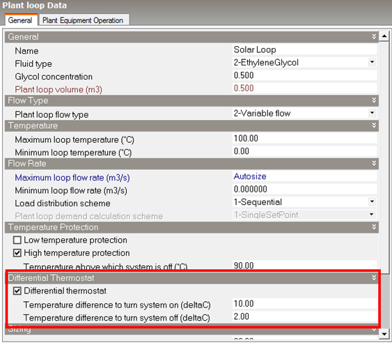
To provide control over the collector loop, a differential thermostat option is incorporated within the solar loop dialog. The differential thermostat compares the temperature in the water heater to the temperature in a collector so that the loop pump is only turned on when there is a useful heat gain.
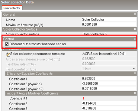
There is an option on the solar collector dialog to allow you to select which collector will act as the sensor for the thermostat. The outlet temperature from the water heater is used as the location for the other thermostat sensor.
Note: If the two temperature differences on the solar collector dialog are too close, it is possible for the system to turn on and off rapidly without much useful heat gain. This can also occur if the flow rate through the collector is too high. Without flow the fluid in the collector heats up more quickly; when high flow is turned on, all of the hot fluid is removed and the temperature drops, forcing the system off again.
In climates with a cold season, the solar heating system must be designed to avoid the risk of fluid freezing in the solar collector or exposed pipes and causing damage. There are several strategies that can minimise the risk.
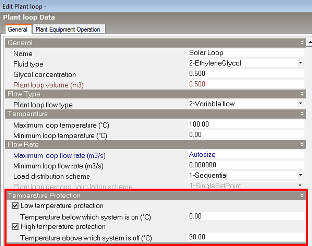
In addition to freeze prevention, it is also necessary to prevent the system from becoming too hot. This is usually a safety issue for the water heater. For this case it is important to have a high temperature cut-off to stop the pump before damaging the water heater. This is accomplished using the High temperature protection setting on the solar loop dialog (see above).
This ratio is the minimum system air flow rate divided by the maximum system air flow rate. The value must be between 0 and 1. For constant volume systems the ratio should be set to 1. Note that this ratio should be set to reflect what the user expects the system flow rate to be when maximum heating demand occurs. This ratio is used in calculating the central system heating capacity. Thus if the system is VAV with the zone VAV dampers held at minimum flow when there is a zone heating demand, this ratio should be set to the minimum flow ratio. If the zone VAV dampers are reverse action and can open to full flow to meet heating demand, this ratio should be set to 1.