The pitched roof block form automatically generates a pitched roof from a perimeter drawn on a horizontal plane. Pitched roof blocks can be created using any perimeter shape (polygon, rectangle or circle):
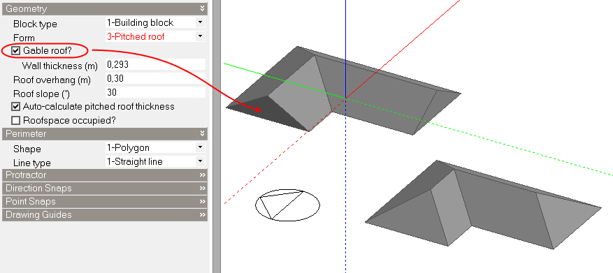
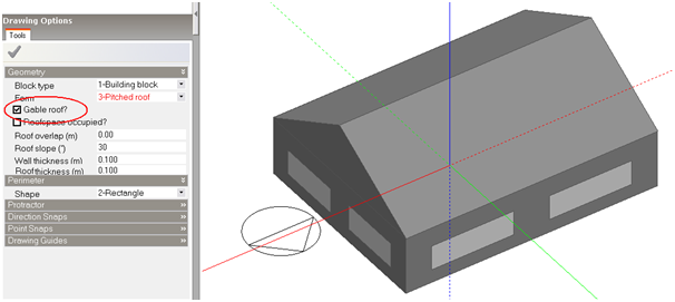
The slope of the roof is defined using the Roof slope setting in the Drawing options data panel. A pitched roof can be created with hips or gable ends using the Gable roof setting:
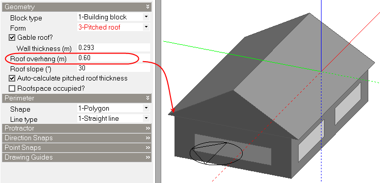
If you draw a pitched roof on top of an existing block, you can control the overhang or the depth of the roof eaves using the Roof overhang setting:
 See also the Basic Drawing Tools 4 Tutorial
Where roofs are to be created on top of conventional blocks that contain voids and the voids are to be automatically incorporated within the pitched roof, the Automatically include voids from lower blocks Model options switch must be switched on before drawing the roof perimeter.
Check this option if the roof is to have vertical gable ends (see above). If this option is not checked then the roof geometry will be a 'hip roof'.
The extent to which the roof forms an overhang over the zones below. if the Auto-calculate pitched roof thickness option is checked then the overhang displayed in the model and also the overhang modelled in the simulation will be exactly the value of Roof overhang entered here.
The slope of the roof to be generated measured from horizontal.
If the roofspace is flagged as being unoccupied (this option is left unchecked) then a series of changes are made to the block attributes:
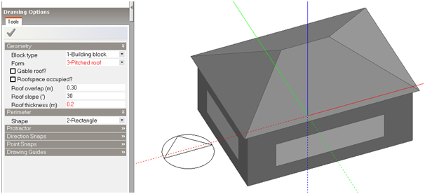
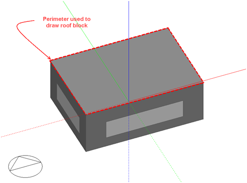
This section describes the automatic DesignBuilder pitched roof geometry generation with reference to an example roof created by drawing a rectangular perimeter with a roof overhang of 0.3m and a roof slab thickness of 0.2m:
Roof perimeters are drawn using the perimeters of lower adjacent blocks:
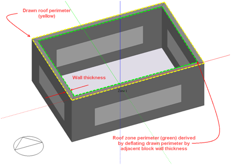
The software first creates the roof zone (this would be the zone written to the EnergyPlus IDF file) by first identifying the wall thickness of the adjacent lower block and then deflating the drawn perimeter by this thickness to obtain the basic roof zone perimeter. The resulting roof zone perimeter is then guaranteed to coincide with the lower adjacent zone perimeter(s) in the absence of a roof overhang:
If a roof overhang is specified, the basic roof zone perimeter is then inflated by the roof overhang:
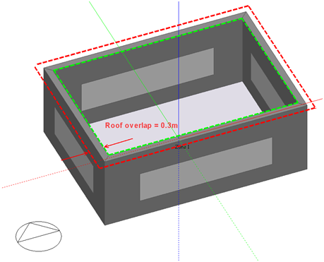
The roof zone is then completed by identifying the skeleton of the perimeter and applying the specified slope to the resulting segments. The base of the roof zone now overlaps the lower adjacent zone(s) by the specified roof overhang:
Note: In the case where a roof perimeter is drawn on top of several blocks having different wall thicknesses, the software identifies the wall thickness having the longest perimeter and uses that thickness to derive the roof zone perimeter. You should be aware that in this case the specified roof overhang will only be guaranteed where the roof overlaps blocks having the same wall thickness as that identified for the roof zone perimeter.
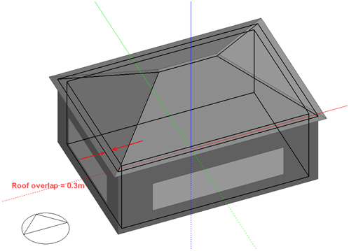
The roof building block slabs are then created by extruding the roof zone surfaces outward along a normal to the surfaces by a distance specified using the Roof Thickness setting.
The perimeter of the resulting roof block will extend beyond the roof zone perimeter by a distance (d in the illustration) determined by the specified roof thickness:
Note: The overhang created by the formation of the roof slabs (d in the above illustration) is only noticeable in the Edit and Visualisation views and will not be written to the IDF file i.e. unlike the roof zone overlap, it has no effect on the EnergyPlus shading calculations.
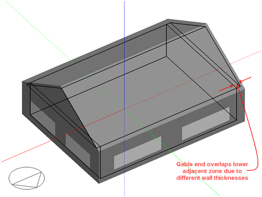
If the Gable roof option is selected, all gable end roof segments (isosceles triangles) are generated to fit flush with the lower adjacent block surface:
If the specified gable wall thickness is different to the wall thickness of the lower adjacent block, an overlap will be created between the roof zone and the lower adjacent zone, which may affect shading calculations in EnergyPlus:
Note: Pitched roof form blocks are automatically configured so that the external walls are not shown on the Edit screen when at block level. This can help when drawing partitions, positioning assembly blocks etc. The option can be reversed using the Display external walls Block display model option if required.