An HVAC loop is used to model air and water distribution systems such as mechanical ventilation systems, hot and chilled water piped distribution systems and condenser water distribution systems. A loop is divided into two sub-loops, a demand sub-loop and a supply sub-loop.
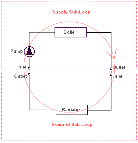
At its simplest, a sub-loop comprises an inlet connection (pipe or duct) which is connected in series via a number of components to an outlet connection. The inlet connection of each loop sub-loop connects with the outlet connection of the other loop sub-loop:
The demand sub-loop is typically that section of a loop from which energy is extracted from a system and the supply sub-loop is that section of a loop to which energy is supplied by the system.
Consequently, supply sub-loops incorporate equipment such as boilers in the case of heating systems or chillers in the case of cooling systems, the supply sub-loop of an air system incorporates items such as heating and cooling coils. The supply sub-loop also contains circulating equipment such as pumps and fans.
Similarly, the demand sub-loop of a heating system includes items such as air conditioning heating coils or zone equipment such as hot water radiators, fan-coil unit heating coils, under-floor heating, etc. and similarly a chilled water demand sub-loop contains equipment such as air condition cooling coils, zone cooled beams, chilled ceilings, etc. The sub-loop of an air loop typically incorporates zone air distribution equipment such as VAV boxes, etc.
There are three main types of loop:
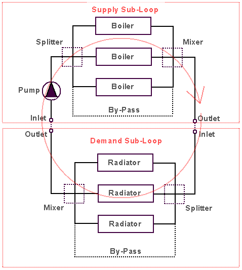
Plant and condenser sub-loops incorporate a flow splitter and a flow mixer which allow a number of parallel branches to be defined. Each parallel branch would normally comprise an inlet connection from the splitter, a component and an outlet connection to the mixer. A by-pass parallel branch (without a component) is also included to ensure flow continuity.
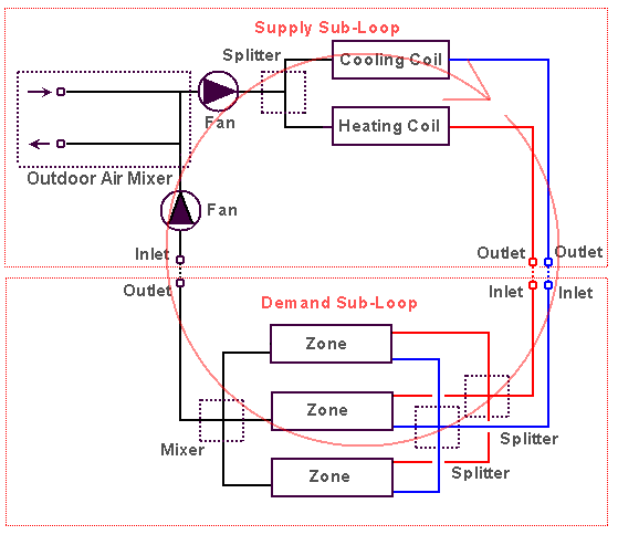
The supply sub-loops for single duct air loops on the other hand generally comprise a single branch which incorporates an inlet connection connected to various components in series including an outdoor air mixer, fans, cooling coils, heating coils, etc. which are in turn connected to an outlet connection. Air loop supply sub-loops do not contain flow splitters or mixers. Demand sub-loops for single duct air loops incorporate the supply path connections to zone air distribution equipment and zone return air path connections. Air loop demand sub-loops also incorporate a flow splitter and a flow mixer allowing air distribution equipment in a number of zones to be connected to the supply and return paths:
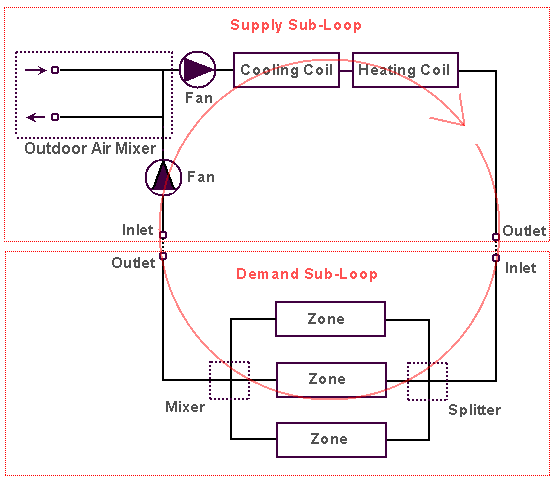
The outdoor air mixer and fan components in DesignBuilder HVAC are incorporated within an air handling unit component. Optionally, additional components such as heat recovery, heating coils, cooling coils, humidifiers and outdoor air pre-treatment coils can also be added to air handling units:
Air supply sub-loops for dual duct systems incorporate two outlet connections, one for the hot duct and one for the cold duct; dual duct supply sub-loops also incorporate a single air splitter to split the flow between the hot and cold ducts:
The demand sub-loops for dual duct air loops similarly contain two inlet connections for hot and cold ducts which can then be connected to zone dual duct air distribution terminals via air splitters and a mixer.
There are nine pre-defined loops in DesignBuilder HVAC, four air loops, four plant loops and one condenser loop: