Adequate
The effect of this option depends on the HVAC model option. When using Simple HVAC, equipment is modelled as having adequately large capacity to meet any heating or cooling demand and setpoint temperatures are always maintained. This option can cause extremely large peaks in heating and cooling delivery to zones and will tend to over-predict heating and cooling energy and under predict discomfort hours. When using Compact HVAC this option is equivalent to Autosize and the Compact HVAC autosizing mechanism is used to size the components and flow rates to ensure that the required comfort conditions are met.
Manual
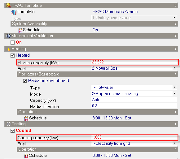
Heating and cooling capacity Model Data must be entered manually. Choose this option if you have specific heating and cooling capacity data you wish to use and do not want it to be overwritten when model data or model options change.
If you would like DesignBuilder to calculate the heating and cooling sizes and also maximum supply flow if you are using Compact HVAC you should follow this procedure:
- Switch to the Autosize option.
- Run heating and cooling design calculations.
- If you are using Compact HVAC also run a simulation.
- Switch to the Manual option.
- You should now see the heating and cooling sizes shown for each zone in the HVAC model data.
- If you are using Compact HVAC then you can also copy the Maximum supply flow in m3/s from the epluszsz.csv file. This can be found in the EnergyPlus folder straight after a Compact HVAC system simulation. The Maximum supply flow data is the bottom row labelled 'Peak Vol Flow (m3/s)'.
Manual Capacity - Compact HVAC
The most accurate way to define heating and cooling capacities is to use a Compact HVAC unitary single zone system. This allows the heating and cooling coil capacities to be directly transferred to the EnergyPlus HVAC definition without the need to convert to maximum air flow rates as in Simple HVAC.
More on manual sizing with Compact HVAC
Manual Capacity - Simple HVAC
The way the DesignBuilder manual cooling capacity setting works with Simple HVAC is dictated by the mechanism provided by the EnergyPlus ZoneHVAC:IdealLoadsAirSystem that is used by DesignBuilder in Simple HVAC. The EnergyPlus ideal loads system specifies cooling supply conditions and maximum supply air flow rate, whereas in the DesignBuilder interface, the user enters a maximum cooling capacity. To convert from the maximum capacity entered on the dialog to a maximum supply air flow rate, DesignBuilder uses a formula:
More on manual capacity and Simple HVAC
This equation works fine when the zone temperature setpoint is met, but when the zone temperature rises above the cooling setpoint temperature then the cooling supplied by the supply air will rise above the maximum value defined for the zone.
Tip: A useful workaround to the above issue is to use a supply air temperature of 99°C for heating and -99°C for cooling. The higher temperature differences involved with these supply temperatures reduce the error when the inside temperature differs from the setpoint used. In this case, the larger delta T value helps to apply a more accurate manual capacity value in the above equation. With the above supply air temperature settings you should find that you get correct maximum capacity when the zone is heated/cooled to it's setpoint, but if the setpoint is not yet achieved then heating/cooling rates will be slightly higher than the maximum capacity value specified.
Note: When using Simple HVAC with operative temperature control and manually entered coil sizes, the DeltaT value used in the above max supply flow rate calculation is reduced by 10°C in DesignBuilder as a very approximate way to account for the lower air temperatures in the zone during hot days with high radiant temperatures. Without this correction, the effective cooling coil capacity would be reduced below the user-defined value when simulated air temperatures are reduced below the operative setpoint temperature to compensate for high radiant temperatures. This correction results in a (at times considerable) over-estimate of cooling capacity when zone air temperature is close to operative setpoint temperature.
Autosize
Autosize is the default option where heating and cooling capacities are always calculated prior to each simulation and the heating and cooling capacity model data is not displayed. When using Simple HVAC the heating and cooling design calculations will be run as required before the simulation to calculate the required sizes. When using Compact HVAC the components and flow rates are sized using the EnergyPlus autosizing mechanism to ensure that the required comfort conditions are met. In this case heating and cooling autosizing calculations are done internally within EnergyPlus and no extra autosizing calculations are carried out by DesignBuilder.
Autosize when not set
In this case heating and cooling capacities are autosized and loaded into model data following heating and cooling design simulations. If Capacity model data is not present before a simulation, it is generated by automatically by carrying out heating and cooling design calculations and is written into the HVAC model data.
You should be aware that when using the Autosize when not set option, the heating/cooling zone capacity model data is not treated the same way as other calculated results. In general, calculated results are deleted when any edit is made to the building model, but this is not the case for zone capacity model data. This is only updated when:
- There is no heating/cooling capacity data (the value is either blank or zero when heating/cooling is switched on) and a simulation is requested. In this case the appropriate design calculations are carried out to fill in the capacity data, before the simulation.
- The appropriate design calculation is carried out by clicking on the Heating/Cooling design tab.
- Model Options change. In this case zone HVAC capacity is deleted.
If you always want the heating capacity to be kept up-to-date with your model and do not have any specific capacity sizes you wish to use, you should consider using the Autosize option. This will cause autosizing to be carried out prior to every simulation.
You can change heating capacities by hand if you wish but you should bear in mind that, if Model options change, all heating and cooling capacities are reset to zero. Set the option to Manual to avoid this happening.