Primary/Secondary Chilled Water Plant Loop
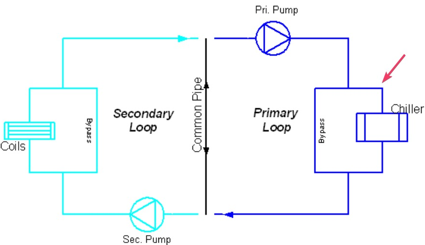
The primary/secondary chilled water plant loop uses the EnergyPlus Common Pipe Simulation mechanism to represent a chilled water circuit comprising both primary and secondary pumped sub-loops. The primary sub-loop incorporates one or more chillers connected in either series or parallel, flow splitter and flow mixer together with a circulating pump.
By default, the chiller has a water cooled condenser and connections are included to enable the condenser to be connected up to a condenser loop. Air cooled chillers can also be selected.
The primary sub-loop also includes a scheduled temperature setpoint manager which is set up by default to control the sub-loop outlet temperature at a constant 6°C.
The secondary sub-loop includes a scheduled temperature setpoint manager which is pre-defined to control the sub-loop inlet temperature at a constant 6°C but the schedule defining this temperature can be replaced with any required alternative. The secondary sub-loop also incorporates a flow splitter and flow mixer in order that the loop can be connected to cooling plant components.
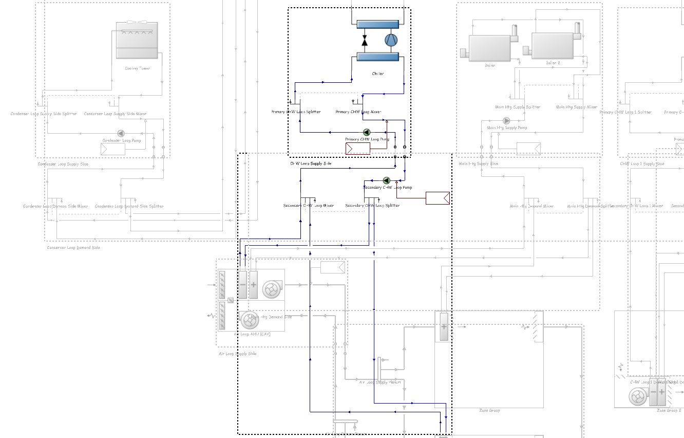
Note: In an EnergyPlus common-pipe (primary-secondary) loop the pump must be located on the first (inlet) branch of the half-loop. Branch-level pumps located just ahead of a chiller, as shown by the red arrow in the layout below, are not supported.
Use the common-pipe option only when a single loop pump on the primary side is acceptable. If your project includes a pump mounted directly at each chiller, consider one of the alternative modelling approaches outlined in this Knowledge Base article, rather than attempting to reposition the pump within a single common-pipe loop - something that EnergyPlus does not currently support.
See also: