The Unitary Generic AHU is intended to replace all other AHUs, although other system types are still available. This system is unique in that it can accommodate all fan and coil types whereas other AHUs are specific to the type of fan and coil available for simulation.
The generic unitary AHU incorporates an outdoor air system and a supply fan (OnOff, ConstantVolume, VariableVolume). There are also options for night cycle operation, a heat recovery system, an economiser, pre-heat and pre-cool coils and an extract fan. Additional components such as heating coils, cooling coils and humidifiers may also be added.
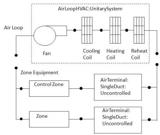
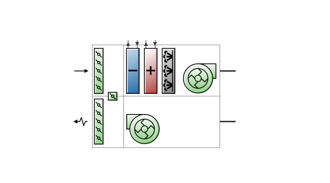
The Unitary AHU consists of a fan component (OnOff, ConstantVolume or VariableVolume), a cooling coil component, a heating coil component, and a reheat coil as shown in the schematic diagram above. For draw-through configurations, the fan is placed directly after the heating coil. If dehumidification control is selected, a reheat coil component is also required. If the reheat coil is present and the Dehumidification control type input is not specified as 2-Cool reheat, the reheat coil will not be active.
In addition, the control zone and the system design operating conditions are specified in the unitary system inputs.
This field contains the identifying name for the unitary AHU. It is read-only.
Select the type of fan for the unitary system from the following options:
1-Constant volume, used when the Fan operating mode schedule values are never 0 and the fan operates continuously.
2-Variable volume, used for variable air volume systems or multi or variable-speed coils.
3-On/Off, used when the fan cycles on and off with the cooling or heating coil (i.e. Fan operating mode schedule values are at times 0).
Select from the following options:
1-Blow through, a blow through fan where the unit consists of a fan followed by the main cooling and heating coils and supplemental heating coil. The fan “blows through” the cooling and heating coils.
2-Draw through, a draw through fan where the unit consists of the main cooling/heating coil(s) followed by a fan, with the supplemental heater located at the outlet of the fan. The fan “draws air through” the cooling/heating coil(s).
Select a schedule that defines the supply air fan operating mode schedule. The fan operating mode may vary during the simulation based on time of day or with a change of season.
Schedule values of 0 denote that the unitary system supply air fan and the heating or cooling coil cycle on and off together to meet the heating or cooling load (aka AUTO fan).
Schedule values other than 0 denote that the supply fan runs continuously while the heating or cooling coil cycles to meet the load.
Note: The 3-Single Zone VAVControl type is only active when the supply air fan runs continuously, and during cycling fan operation the 1-Load Control type model is used.
Unitary systems don’t need the night cycle manager used by the standard generic AHU. Instead this functionality is achieved as follows.
Select the On 24/7 Availability schedule to allow the system to always be on.
Use the Fan operating mode schedule to switch between:
continuous fan operation for ventilation during occupied periods, and,
cycling fan for unoccupied periods to allow the system to cycle on and off as the thermostat requests, and run just enough to meet the load.
Select the schedule which contains information on the availability of the unitary system to operate. A schedule value equal to 0 denotes that the unitary system must be off for that time period. A value greater than 0 denotes that the unitary system is available to operate during that time period. This schedule may be used to completely disable the unitary system as required.
This setting defines the control type for the unitary system, i.e. whether it is load based or setpoint based. Select from these options:
1-Load which requires a Controlling zone to be defined.
2- SetPoint which requires set points at each coil outlet node. A single set point at the outlet of the system is allowed but not recommended. If setpoint control is used and the system represents a heat pump (i.e., cooling and heating coils are both DX coils) then only one of these coils may operate at a time.
3-Single Zone VAV which requires two distinct fan flow rates, namely the Cooling and Heating supply air flow rate and a lower No Load Supply Air Flow Rate which is used during times of reduced cooling or heating loads. This option allows load control at low speed fan until the load exceeds available capacity or the outlet air temperature exceeds the specified limits where the fan speed is then increased. Temperature limits are identified in the input fields for Minimum and Maximum supply air temperature.
Additionally, specific coil types are required for this control type. Allowed cooling coil types are: 1-Water and 3-DX single speed, while the allowed heating coil types are 1-Water, 2-Electric, 3-Fuel and 4-DX single speed. If other coil types are used they are modelled using the 1-Load based control method.
Both 1-Load and 3-Single Zone VAV Control types require a Controlling zone to be defined.
When Control type is set to 1-Load or 3-Single Zone VAV you must select the zone where the thermostat controlling the unitary system is located.
This setting allows you to select the type of dehumidification control. The following options are available:
1-None - the default option where the AHU meets sensible loads only with no active dehumidification control. This option is required when Control type is set to 3-Single Zone VAV.
2-Cool reheat - where the AHU cools beyond the dry-bulb temperature set point as required to meet the high humidity setpoint.
This setting defines the latent load control method. Available choices are:
1-Sensible only, the default option, will operate to meet only a sensible load and is also required when the 3-Single Zone VAV Control type is selected.
2-Latent only will operate to meet only a latent load
3-Latent with sensible will operate to meet the latent load only if there is a sensible load.
4-Latent or sensible will operate to meet either a latent or sensible load.
This numeric field contains the design operating air outlet temperature (in °C or °F) when the unitary system is cooling.
When the Use DOAS DX cooling coil checkbox is checked, this is the DX cooling coil's leaving minimum air temperature for frost control. The DX cooling coil leaving air temperature is not allowed to be lower than this minimum air temperature. The DX cooling coil frost controller adjusts or limits the desired coil outlet air setpoint temperature when the coil outlet temperature exceeds this minimum temperature limit specified. The minimum and maximum values of this input field are 0.0°C and 7.5°C respectively. The default value is 2.0°C.
When using the 3-Single Zone VAV Control type, enter the minimum air temperature limit for reduced fan speed in cooling mode. In this case the maximum limit for the minimum supply air temperature is 20.0°C. Additionally, for the 3-Single Zone VAV Control type, this input does not limit the minimum supply air temperature resulting from cooling coil operation at high fan speed.
This numeric field contains the design operating air outlet temperature (in °C or °F) when the unitary system is heating. When using the 3-Single Zone VAV Control type, enter the maximum air temperature limit for reduced fan speed in heating model. In this case, this input does not limit the maximum supply air temperature resulting from heating or supplemental heating coil operation at high fan speed. This field is autosizable.
This setting defines the supply air flow method during cooling operation. Available choices are:
1-Supply air flow rate.
2-Flow per floor area.
3-Fraction of autosized cooling value.
4-Flow per cooling capacity.
For each of the choices, a corresponding air flow rate for cooling must be specified (see below). If the system does not have a cooling coil a 0 may be entered for cooling air flow rate and/or no load supply air flow rate to turn the fan off when cooling is not required.
This setting defines the supply air flow rate leaving the unitary system (in m3/s or ft3/min) when the cooling coil is operating. It is required when the Cooling supply air flow rate method is 1-Supply air flow rate. This field is autosizable.
This setting defines the supply air flow rate per floor area leaving the unitary system (in m3/s or ft3/min) when the cooling coil is operating. It is required when the Cooling supply air flow rate method is 2-Flow per floor area. This field is autosizable.
This setting defines the fraction of autosized supply air flow rate leaving the unitary system when the cooling coil is operating. It is required when the Cooling supply air flow rate method is 3-Fraction of autosized cooling value.
This numeric field defines the supply air flow rate per unit of capacity leaving the unitary system when the cooling coil is operating. The units are or m3/s/W or (ft3/min)/(Btu/h). It is required when the Cooling supply air flow rate method is 4-Flow per cooling capacity.
This setting defines the supply air flow method during heating operation. Available choices are:
1-Supply air flow rate.
2-Flow per floor area.
3-Fraction of autosized heating value.
4-Flow per heating capacity.
For each of the choices, a corresponding air flow rate for heating must be specified (see below). If the system does not have a heating coil a 0 may be entered for heating air flow rate and/or no load supply air flow rate to turn the fan off when heating is not required.
This setting defines the supply air flow rate leaving the unitary system (in m3/s or ft3/min) when the heating coil is operating. It is required when the Heating supply air flow rate method is 1-Supply air flow rate. This field is autosizable.
This setting defines the supply air flow rate per floor area leaving the unitary system (in m3/s or ft3/min) when the heating coil is operating. It is required when the Heating supply air flow rate method is 2-Flow per floor area. This field is autosizable.
This setting defines the fraction of autosized supply air flow rate leaving the unitary system when the heating coil is operating. It is required when the Heating supply air flow rate method is 3-Fraction of autosized heating value.
This numeric field defines the supply air flow rate per unit of capacity leaving the unitary system when the heating coil is operating. The units are or m3/s/W or (ft3/min)/(Btu/h). It is required when the Heating supply air flow rate method is 4-Flow per cooling capacity.
This setting defines the supply air flow method when neither cooling or heating is required. Available choices are:
1-Supply air flow rate.
2-Flow per floor area.
3-Fraction of autosized cooling value.
4-Fraction of autosized heating value.
5-Flow per cooling capacity.
6-Flow per heating capacity.
For each of these options, a corresponding air flow rate must be specified. The following "No load supply air flow rate" etc fields are also used to specify the lower air flow rate for the 3-Single Zone VAV control method with recommendations of greater than or equal to 67% of the Cooling or Heating Supply Air Flow Rate when any DX coil is used and 50% for other coil types.
This numeric setting defines the supply air flow rate leaving the unitary system (in m3/s or ft3/min) when neither cooling or heating is required (i.e., when the main cooling/heating coils and supplemental heater are off but the supply air fan operates). It is only used when the unitary system operating mode is specified as continuous fan operation. It is required when the No load supply air flow rate method is 1-Supply air flow rate.
This field is autosizable. If this field is autosized, then it is sized to the minimum of the heating and cooling lowest speed supply air flow rate. If the unitary system operating mode is specified as continuous fan operation and this value is set to zero, then the model assumes that the supply air flow rate when no cooling/heating is needed is equal to the supply air flow rate when the compressor was last operating (for cooling operation or heating operation).
This numeric setting defines the supply air flow rate per floor area leaving the unitary system (in m3/s or ft3/min) when neither cooling or heating coil is operating. It is required when the No load supply air flow rate method is 2-Flow per floor area. This field is autosizable.
This numeric field defines the fraction of autosized supply air flow rate leaving the unitary system when neither cooling or heating coil is operating. It is required when the No load supply air flow rate method is 3-Fraction of autosized cooling value.
This numeric setting defines the fraction of autosized supply air flow rate leaving the unitary system when the neither cooling or heating coil is operating. It is required when the No load supply air flow rate method is 4-Fraction of autosized heating value.
This numeric setting defines the supply air flow rate per unit of capacity leaving the unitary system when neither cooling or heating is operating. It is required when the No load supply air flow rate method is 5-Flow per cooling capacity.
This numeric setting defines the supply air flow rate per unit of capacity leaving the unitary system when neither cooling or heating is operating. It is required when the No load supply air flow rate method is 6-Flow per heating capacity.
Check the checkbox to include an extract fan.
This numeric field is used to adjust heat pump heating capacity with respect to DX cooling capacity. It is used only for DX heat pump configurations (i.e., when DX cooling and DX heating coils are used).
Important Note: In DesignBuilder v2025.1, this option should be left unchecked due to a bug in EnergyPlus v23.1: #11378.
This input field enables DX Cooling coils to be used for 100% outdoor air dedicated outdoor air system applications.
When this option is checked, the DX coil is used as 100% outdoor DX coil.
When it is unchecked, the DX coil is used as regular DX coil.
This option is not available when the 3-Single Zone VAV Control type is selected.
This numeric field contains the maximum on-off cycling rate for the compressor, which occurs at 50% run time fraction. Suggested values for Maximum cycling rate are shown below(Henderson et al. 1999):
| Heat Pump Condition | Recommended Values |
| Typical | 2.5 |
| Good | 2.5 |
| Poor | 3.0 |
This numeric field contains the time constant for the cooling coil’s capacity to reach steady state after startup. Suggested values are shown in the table below (Henderson et al. 1999):
| Heat Pump Condition | Recommended Values |
| Typical | 60 |
| Good | 60 |
| Poor | 60 |
This numeric field contains the time delay for the heat pump supply air fan to shut off after the compressor cycles off in seconds. This value can be obtained from the manufacturer or the heat pump catalog. Enter a value of zero when the heat pump’s fan operating mode is continuous. Suggested value is 60 seconds.
This numeric field contains the fraction of on-cycle power use to adjust the part load fraction based on the off-cycle power consumption due to crankcase heaters, controls, fans, and etc. Suggested value values are shown in the table below. (Henderson et al. 1999):
| Heat Pump Condition | Recommended Values |
| Typical | 2.5 |
| Good | 2.5 |
| Poor | 3.0 |
This field defines ancillary electrical power (W) consumed during the on-cycle period (i.e., when the cooling or heating coil is operating). The model assumes that this ancillary power does not contribute to heating the supply air.
This field defines ancillary electrical power (W) consumed during the off-cycle period (i.e., when the cooling and heating coil are not operating). The model assumes that this ancillary power does not contribute to heating the supply air.
This numeric field defines the outdoor air dry-bulb temperature above which the heat pump supplemental heating coil is disabled. The temperature for this input field must be less than or equal to 21°C.
You can set up Mixed mode controls for the AHU to model optimal interaction between the natural ventilation system (Scheduled or Calculated) and the AHU.
Refer to the main HVAC tab Mixed Mode section for details on the options available.
Note: If mixed mode is activated here on the AHU dialog, then any mixed mode settings for connected zones on the HVAC tab will be overriden by these mixed mode settings.