Component blocks and assemblies can be used for CFD analyses to simply allow for the effect of obstructions on the airflow. However, they also allow the definition of CFD boundary attributes to enable them to act as constant temperature surfaces or heat flux sources and can also be modified to behave as non-solids to allow air to pass through them.
Note: Component blocks and assemblies defined at block level do not affect EnergyPlus simulations
CFD attributes for component blocks are inherited down from the building level to component blocks located at both building and building block levels. CFD attributes for component blocks are accessed on the CFD model data tab.
The CFD assembly library that is provided with DesignBuilder contains a number of pre-defined assemblies that can be used to add items such as occupants, radiators and furniture. Some of these pre-defined assemblies already have CFD boundary attributes associated with them, e.g. standing occupant assemblies have a defined convective heat flux of 56W. You can also define your own assemblies for use in CFD analyses and you will find details of how to do this in the Assembly library section.
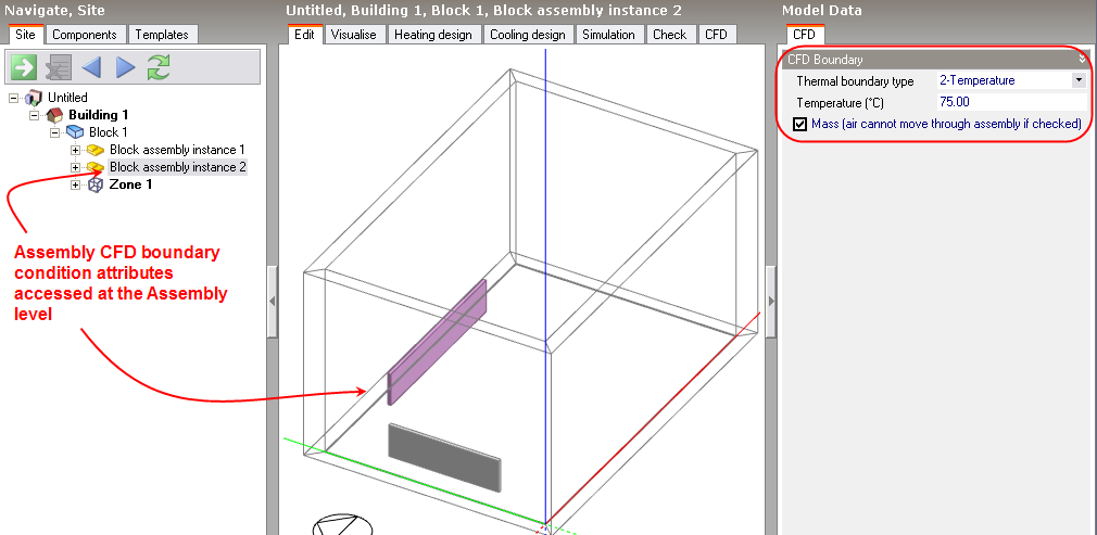
CFD attributes for component assemblies are inherited from the parent assembly to instances of the assembly at the building and building block levels. CFD attributes for assemblies are accessed from the CFD tab after moving down to an assembly instance level by clicking on it in the navigator or double-clicking on it in the Edit screen. It is important to understand that if you change an attribute for a specific instance of an assembly, the attributes will be changed for all other instances of the same assembly.
The following CFD boundary settings are available for both component blocks and component assemblies:
Thermal boundary type: The thermal boundary type can be set to one of the following:
If the thermal boundary type has been set to 2-Temperature, enter the temperature of the block.
If the thermal boundary type has been set to 3-Flux, enter the convective only portion of the heat emission of the block. If you know the total heat flux then you can calculate the convective part by multiplying by (1-radiant fraction). For modelling building occupants you can assume a radiant fraction of 0.5. You can search the DesignBuilder help using "radiant fraction" as the search term to find more example radiant fractions for different types of equipment.
Important Note: In the case of assemblies used to apply a heat flux boundary condition, the heat flux data on the CFD tab of the component blocks can be treated in one of 2 ways depending on whether or not it inherits this data from the assembly above:
a) When inheriting from the assembly above the same heat flux data as for the parent assembly appears in blue on the CFD tab, but DesignBuilder doesn't use this directly. Instead the data is applied as if it is the total for the whole assembly and the actual value for this component block is reduced by a proportion equal to the ratio of the component volume to the volume of the whole assembly.
b) When hard set heat flux data is entered (data shown in red on the CFD tab) this is used directly in CFD calculations and spread evenly around the component block surfaces.
Determines whether or not the block will act as a physical obstruction to the surrounding flow. In some cases, it may be desirable to fix the temperature or flux of the component but allow air to pass through the block, e.g. to represent an occupancy flux throughout a large volume without needing to locate individual occupants.