
![]() Coil:Cooling:DX:SingleSpeed
Coil:Cooling:DX:SingleSpeed
Used in:
- PTAC,
- PTHP,
- Unitary Heat Cool,
- Unitary Heat Pump
|
|
|
Used in:
|
The DX single speed cooling coil model and data are quite different from that for the heating and cooling water coils. The simple water coils use an NTU-effectiveness heat exchanger model. The single speed DX coil model uses performance information at rated conditions along with curve fits for variations in total capacity, energy input ratio and part-load fraction to determine performance at part-load conditions. Sensible/latent capacity splits are determined by the rated sensible heat ratio (SHR) and the apparatus dewpoint/bypass factor (ADP/BF) approach. This approach is analogous to the NTU-effectiveness calculations used for sensible-only heat exchanger calculations, extended to a cooling and dehumidifying coil.
This DX cooling coil input requires an availability schedule, the rated total cooling capacity, the rated SHR, the rated COP, and the rated air volume flow rate. The latter 4 inputs determine the coil performance at the rating point (air entering the cooling coil at 26.7°C dry-bulb/19.4°C wet-bulb and air entering the outdoor condenser coil at 35°C dry-bulb/23.9°C wet-bulb). The rated air volume flow rate should be between .00004027 m3/s and .00006041 m3/s per watt of rated total cooling capacity (300 to 450 cfm/ton).
See section “DX Cooling Coil Model” in the EnergyPlus Engineering Document for further details regarding this model.
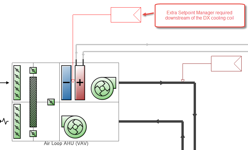
Important Note: When a Single speed DX cooling coil is placed in an AHU upstream from a heating coil, it is important to include an extra SPM immediately downstream of the cooling coil. The extra SPM should include all of the same settings as the SPM downstream of the AHU. See screenshot below. This use of a duplicate SPM in this way is the workaround recommended by the EnergyPlus support team for an issue which is expected to be fixed in versions of E+ after v8.5.
A unique auto-assigned name for an instance of a DX cooling coil. Any reference to this DX coil by another object will use this name.
The total, full load cooling capacity (sensible plus latent) (in W or Btu/h) of the DX coil unit at rated conditions. These are: air entering the cooling coil at 26.7°C dry-bulb/19.4°C wet-bulb, air entering the outdoor condenser coil at 35°C dry-bulb/23.9°C wet-bulb (The 23.9°C wet-bulb temperature condition is not applicable for air-cooled condensers which do not evaporate condensate), and a cooling coil air flow rate fan heat is NOT included. When used in a heat pump, the rated total cooling capacity should be within 20% of the rated total heating capacity, otherwise a warning message is issued.
The sensible heat ratio (SHR=sensible capacity divided by total cooling capacity) of the DX cooling coil at rated conditions (air entering the cooling coil at 26.7°C dry-bulb/19.4°C wet-bulb, air entering the outdoor condenser coil at 35°C dry-bulb/23.9°C wet-bulb, and a cooling coil air flow rate defined by field “rated air volume flow rate” below). Both the sensible and total cooling capacities used to define the Rated SHR should be “gross” (i.e., supply air fan heat is NOT included).
The coefficient of performance (cooling power output in watts divided by electrical power input in watts) of the DX cooling coil unit at rated conditions (air entering the cooling coil at 26.7°C dry-bulb/19.4°C wet-bulb, air entering the outdoor condenser coil at 35°C dry-bulb/ 23.9°C wet-bulb, and a cooling coil air flow rate defined by field “rated air volume flow rate” below). The input power includes electric power for the compressor(s) and condenser fan(s) but does not include the power consumption of the supply air fan. The cooling power output is the value entered above in the field “Rated Total Cooling Capacity (gross)”.
The air volume flow rate (in m3/s or ft3/min), across the DX cooling coil at rated conditions. The rated air volume flow rate should be between 0.00004027 m3/s and 0.00006041 m3/s per watt of rated total cooling capacity (300 to 450 cfm/ton). The rated total cooling capacity, rated SHR and rated COP should be performance information for the unit with air entering the cooling coil at 26.7°C dry-bulb/19.4°C wet-bulb, air entering the outdoor condenser coil at 35°C dry-bulb/23.9°C wet-bulb, and the rated air volume flow rate defined here.
This field is the electric power for the evaporator (cooling coil) fan per air volume flow rate through the coil at the rated conditions (in W/(m3/s) or W/(ft3/min)). The default value is 773.3 W/(m3/s) (365 W/1000 cfm). The value must be >= 0.0 and <= 1250 W/(m3/s). This value is only used to calculate Seasonal Energy Efficiency Ratio (SEER), Energy Efficiency Ratio (EER), Integrated Energy Efficiency Ratio (IEER) and the Standard Rating (Net) Cooling Capacity which will be outputs in the EnergyPlus eio file (ref. EnergyPlus Engineering Reference, Single Speed DX Cooling Coil, Standard Ratings). This value is not used for modelling the evaporator (cooling coil) fan during simulations; instead, it is used for calculating SEER, EER, IEER and Standard Rating Cooling Capacity to assist the user in verifying their inputs for modelling this type of equipment.
The name of the schedule that denotes whether the DX cooling coil can run during a given time period. A schedule value greater than 0 (usually 1 is used) indicates that the unit can be on during a given time period. A value less than or equal to 0 (usually 0 is used) denotes that the unit must be off.
The DX Cooling coil requires 5 curves be selected from the Curves database to define coil performance:
The Bi-quadratic performance curve that parameterises the variation of the total cooling capacity as a function of the wet-bulb temperature of the air entering the cooling coil, and the dry-bulb temperature of the air entering the air-cooled condenser coil (wet-bulb temperature if modelling an evaporative-cooled condenser). The output of this curve is multiplied by the rated total cooling capacity to give the total cooling capacity at specific temperature operating conditions (i.e., at temperatures different from the rating point temperatures). The curve is normalized to have the value of 1.0 at the rating point.
The Quadratic or Cubic performance curve that parameterises the variation of total cooling capacity as a function of the ratio of actual air flow rate across the cooling coil to the rated air flow rate (i.e., fraction of full load flow). The output of this curve is multiplied by the rated total cooling capacity and the total cooling capacity modifier curve (function of temperature) to give the total cooling capacity at the specific temperature and air flow conditions at which the coil is operating. The curve is normalized to have the value of 1.0 when the actual air flow rate equals the rated air flow rate.
The Bi-quadratic performance curve that parameterises the variation of the energy input ratio (EIR) as a function of the wet-bulb temperature of the air entering the cooling coil, and the dry-bulb temperature of the air entering the air-cooled condenser coil (wet-bulb temperature if modelling an evaporative-cooled condenser). The EIR is the inverse of the COP. The output of this curve is multiplied by the rated EIR (inverse of rated COP) to give the EIR at specific temperature operating conditions (i.e., at temperatures different from the rating point temperatures). The curve is normalized to a value of 1.0 at the rating point.
The Quadratic or Cubic performance curve that parameterises the variation of the energy input ratio (EIR) as a function of the ratio of actual air flow rate across the cooling coil to the rated air flow rate (i.e., fraction of full load flow). The EIR is the inverse of the COP. The output of this curve is multiplied by the rated EIR and the EIR modifier curve (function of temperature) to give the EIR at the specific temperature and air flow conditions at which the cooling coil is operating. This curve is normalized to a value of
1.0 when the actual air flow rate equals the rated air flow rate.
The Quadratic or Cubic performance curve that parameterises the variation of electrical power input to the DX unit as a function of the part load ratio (PLR, sensible cooling load/steady-state sensible cooling capacity). The product of the rated EIR and EIR modifier curves is divided by the output of this curve to give the “effective” EIR for a given simulation timestep. The part load fraction (PLF) correlation accounts for efficiency losses due to compressor cycling.
The 2 important rules to be followed when setting up this curve are:
Check this option if the degradation of latent cooling capacity is to be modelled. In this case the following four input fields are shown allowing you to enter data relating to the degradation of latent cooling capacity when the supply air fan operates continuously while the cooling coil/compressor cycle on and off to meet the cooling load.
The fan operating mode is determined in the parent object and is considered to either be constant (e.g. AirLoopHVAC:UnitaryCoolOnly) or can be scheduled (e.g. AirLoopHVAC:UnitaryHeatCool). When scheduled, the schedule value must be greater than 0 to calculate degradation of latent cooling capacity. At times when the parent object’s supply air fan operating mode schedule is 0, latent degradation will be ignored. When modelling latent capacity degradation, these next four input fields must all have positive values.
The nominal time (in seconds) after startup for condensate to begin leaving the coil's condensate drain line at the coil's rated airflow and temperature conditions, starting with a dry coil. Nominal time is equal to the ratio of the energy of the coil's maximum condensate holding capacity (J) to the coil's steady-state latent capacity (W). Suggested value is 1000; zero value means the latent degradation model is disabled. The default value for this field is zero. The supply air fan operating mode must be continuous (i.e., the supply air fan operating mode may be specified in other ”parent” objects and is assumed continuous in some objects (e.g., AirloopHVAC:UnitaryCoolOnly) or can be scheduled in other objects [e.g., AirloopHVAC:UnitaryHeatCool]), and this field as well as the next three input fields for this object must have positive values in order to model latent capacity degradation.
The ratio of the initial moisture evaporation rate from the cooling coil (when the compressor first turns off (in W) and the coil's steady-state latent capacity (W) at rated airflow and temperature conditions. Suggested value is 1.5; zero value means the latent degradation model is disabled. The default value for this field is zero. The supply air fan operating mode must be continuous (i.e., the supply air fan operating mode may be specified in other ”parent” objects and is assumed continuous in some objects (e.g., AirloopHVAC:UnitaryCoolOnly) or can be scheduled in other objects [e.g., AirloopHVAC:UnitaryHeatCool]); and this field, the previous field and the next two fields must have positive values in order to model latent capacity degradation.
The maximum on-off cycling rate for the compressor (cycles per hour), which occurs at 50% run time fraction. Suggested value is 3; zero value means latent degradation model is disabled. The default value for this field is zero. The supply air fan operating mode must be continuous (i.e., the supply air fan operating mode may be specified in other ”parent” objects and is assumed continuous in some objects (e.g., AirloopHVAC:UnitaryCoolOnly) or can be scheduled in other objects [e.g., AirloopHVAC:UnitaryHeatCool]); and this field, the previous two fields and the next field must have positive values in order to model latent capacity degradation.
Time constant (in seconds) for the cooling coil's latent capacity to reach steady state after startup. Suggested value is 45. The supply air fan operating mode must be continuous (i.e., the supply air fan operating mode may be specified in other ”parent” objects and is assumed continuous in some objects (e.g., AirloopHVAC:UnitaryCoolOnly) or can be scheduled in other objects [e.g., AirloopHVAC:UnitaryHeatCool]), and this field as well as the previous three input fields for this object must have positive values in order to model latent capacity degradation.
The type of condenser used by the DX cooling coil. Valid choices for this input field are:
The default Condenser type is is 1-Air cooled.
The data below is required only for Condenser type = Evaporatively cooled.
The effectiveness of the evaporative condenser, which is used to determine the temperature of the air entering the outdoor condenser coil as follows:
Tcond inlet = Twbo + (1 - EvapCondEffectiveness) (Tdbo - Twbo)
where:
Tcond inlet = the temperature of the air entering the condenser coil (°C)
Twbo = the wet-bulb temperature of the outdoor air (°C)
Tdbo = the dry-bulb temperature of the outdoor air (°C)
The resulting condenser inlet air temperature is used by the Total Cooling Capacity Modifier Curve (function of temperature) and the Energy Input Ratio Modifier Curve (function of temperature). The default value for this field is 0.9, although valid entries can range from 0.0 to 1.0. This field is not used when Condenser Type = Air Cooled.
If the user wants to model an air-cooled condenser, they should simply specify an air cooled Condenser Type. In this case, the Total Cooling Capacity Modifier Curve (function of temperature) and the Energy Input Ratio Modifier Curve (function of temperature) input fields for this object should reference performance curves that are a function of outdoor dry-bulb temperature.
If you wish to model an evaporative-cooled condenser AND have performance curves that are a function of the wet-bulb temperature of air entering the condenser coil, then you should specify Condenser Type = Evaporatively cooled and the evaporative condenser effectiveness value should be entered as 1.0. In this case, the Total Cooling Capacity Modifier Curve (function of temperature) and the Energy Input Ratio Modifier Curve (function of temperature) input fields for this object should reference performance curves that are a function of the wet-bulb temperature of air entering the condenser coil.
If you wish to model an air-cooled condenser that has evaporative media placed in front of it to cool the air entering the condenser coil, then you should specify Condenser Type = Evaporatively cooled. You must also enter the appropriate evaporative effectiveness for the media. In this case, the Total Cooling Capacity Modifier Curve (function of temperature) and the Energy Input Ratio Modifier Curve (function of temperature) input fields for this object should reference performance curves that are a function of outdoor dry-bulb temperature. Be aware that the evaporative media will significantly reduce the dry-bulb temperature of the air entering the condenser coil, so the Total Cooling Capacity and EIR Modifier Curves must be valid for the expected range of dry-bulb temperatures that will be entering the condenser coil.
The air volume flow rate, (in m3/s or ft3/min), entering the evaporative condenser. This value is used to calculate the amount of water used to evaporatively cool the condenser inlet air. The minimum value for this field must be greater than zero, and this input field is autosizable (equivalent to 0.000144 m3/s per watt of rated total cooling capacity [850 cfm/ton]). This field is not shown for Air cooled condensers.
The rated power of the evaporative condenser water pump (in W or Btu/h). This value is used to calculate the power required to pump the water used to evaporatively cool the condenser inlet air. The default value for this input field is zero, but it is autosizable (equivalent to 0.004266 W per watt [15 W/ton] of rated total cooling capacity). This field is not shown for Air cooled condensers.
This numeric field defines the crankcase heater capacity (in W). When the outdoor air dry-bulb temperature is below the value specified in the input field “Maximum Outdoor Dry-bulb Temperature for Crankcase Heater Operation” (described below), the crankcase heater is enabled during the time that the compressor is not running. If this cooling coil is used as part of an air-to-air heat pump (Ref. UnitarySystem:HeatPump:AirToAir or PackageTerminal: HeatPump:AirToAir), the crankcase heater defined for this DX cooling coil is ignored and the crankcase heater power defined for the DX heating coil (Ref. Coil:Heating:DX:SingleSpeed) is enabled during the time that the compressor is not running for either heating or cooling. The value for this input field must be greater than or equal to 0, and the default value is 0. To simulate a DX cooling coil without a crankcase heater, enter a value of 0.
This numeric field defines the outdoor air dry-bulb temperature (in °C or °F) above which the compressor’s crankcase heater is disabled. The value for this input field must be greater than or equal to 0.0°C, and the default value is 10°C.
This numeric field contains the capacity of the DX coil’s electric evaporative cooler basin heater in (W/K or Btu/h-F). This field only applies for Condenser type = Evaporatively cooled. This field is used in conjunction with the Basin Heater Setpoint Temperature described in the following field. The basin heater electric power is equal to this field multiplied by the difference between the basin heater set point temperature and the outdoor dry-bulb temperature. The basin heater only operates when the DX coil is off, regardless of the basin heater schedule described below. The basin heater capacity must be greater than or equal to zero.
This numeric field contains the set point temperature (in ˚C or ˚F) for the basin heater described in the previous field. This field only applies for Condenser type = Evaporatively cooled. The basin heater is active when the outdoor air dry-bulb temperature falls below this setpoint temperature, as long as the DX coil is off. This set point temperature must be greater than or equal to 2˚C.
This alpha field contains the name of the basin heater operating schedule. This field only applies for Condenser type = Evaporatively cooled. The basin heater operating schedule is assumed to be an on/off schedule and the heater is available to operate any time the schedule value is greater than 0. The basin heater operates when scheduled on and the outdoor air dry-bulb temperature is below the set point temperature described in the previous field. Regardless of this schedule, the basin heater can only operate when the DX coil is off.
For DX cooling coils located in a unitary system the run settings can be controlled.
Check this option if the coil will operate to meet a sensible load as determined by the inlet node dry-bulb temperature and the dry-bulb temperature setpoint on the control node. When this option is checked the unit will run if there is a sensible load, otherwise the unit will not run if there is only a sensible load.
Check this option if the coil will operate to meet a latent load as determined by the inlet node humidity ratio and the max humidity setpoint on the control node. When this option is checked the coil will operate if there is a latent load. If both sensible and latent loads exist, the system will operate to maintain the temperature set point. When only a latent load exists, the system will operate to meet the humidity ratio set point and requires the use of a heating coil and heating coil outlet air temperature set point manager downstream of this cooling coil to maintain the temperature set point. If this option is not checked then this coil will not run if there is only a latent load.
This checkbox should be checked if the DX coil is to be placed in an AHU used for DOAS. In this case the Rated air flow rate to Rated cooling capacity ratio for 100% dedicated outdoor air (DOAS) application DX cooling coils should be between 0.00001677 (m3/s)/W (125 cfm/ton) and 0.00003355 (m3/s)/W (250 cfm/ton).
HVAC,Average,DX Coil Total Cooling Rate[W]
HVAC,Sum,DX Coil Total Cooling Energy[J]
HVAC,Average,DX Coil Sensible Cooling Rate[W]
HVAC,Sum,DX Coil Sensible Cooling Energy[J]
HVAC,Average,DX Coil Latent Cooling Rate[W]
HVAC,Sum,DX Coil Latent Cooling Energy[J]
HVAC,Average,DX Cooling Coil Electric Power[W]
HVAC,Sum,DX Cooling Coil Electric Consumption[J]
HVAC,Average,DX Cooling Coil Runtime Fraction
If not part of UnitarySystem:HeatPump:AirToAir:
HVAC,Average,DX Cooling Coil Crankcase Heater Power[W]
HVAC,Sum,DX Cooling Coil Crankcase Heater Consumption[J]
Evaporative-cooled condenser:
HVAC,Average,DX Cooling Coil Condenser Inlet Temp[C]
HVAC,Sum,DX Cooling Coil Evap Condenser Water Consumption[m3]
HVAC,Average,DX Cooling Coil Evap Condenser Pump Electric Power[W]
HVAC,Sum,DX Cooling Coil Evap Condenser Pump Electric Consumption[J]
HVAC,Average,DX Cooling Coil Basin Heater Electric Power[W]
HVAC,Sum,DX Cooling Coil Basin Heater Electric Consumption[J]
Additional variables for Coil:Cooling:DX:TwoStageWithHumidityControlMode
only:
HVAC,Average,DX Cooling Coil Stage 2 Runtime Fraction
HVAC,Average,DX Cooling Coil Dehumidification Mode
HVAC,Average,DX Cooling Coil Condensate Volumetric Flow Rate [m3/s]
Zone,Meter,Condensate:OnSiteWater [m3]
This field is the total (sensible and latent) cooling rate output of the DX coil in Watts. This is determined by the coil inlet and outlet air conditions and the air mass flow rate through the coil.
This is the total (sensible plus latent) cooling output of the DX coil in Joules over the timestep being reported. This is determined by the coil inlet and outlet air conditions and the air mass flow rate through the coil. This output is also added to a report meter with Resource Type = EnergyTransfer, End Use Key = CoolingCoils, Group Key = System (Ref. Report Meter).
This output is the moist air sensible cooling rate output of the DX coil in Watts. This is determined by the inlet and outlet air conditions and the air mass flow rate through the coil.
This is the moist air sensible cooling output of the DX coil in Joules for the timestep being reported. This is determined by the inlet and outlet air conditions and the air mass flow rate through the coil.
This is the latent cooling rate output of the DX coil in Watts. This is determined by the inlet and outlet air conditions and the air mass flow rate through the coil.
This is the latent cooling output of the DX coil in Joules for the timestep being reported. This is determined by the inlet and outlet air conditions and the air mass flow rate through the coil.
This output is the electricity consumption rate of the DX coil compressor and condenser fan(s) in Watts. This value is calculated for each HVAC system timestep, and the results are averaged for the timestep being reported.
This is the electricity consumption of the DX coil compressor and condenser fan(s) in Joules for the timestep being reported. This output is also added to a report meter with Resource Type = Electricity, End Use Key = Cooling, Group Key = System (Ref. Report Meter).
This is the runtime fraction of the DX coil compressor and condenser fan(s) for the timestep being reported.
This is the average electricity consumption rate of the DX coil compressor’s crankcase heater in Watts for the timestep being reported.
This is the electricity consumption of the DX coil compressor’s crankcase heater in Joules for the timestep being reported. This output is also added to a report meter with Resource Type = Electricity, End Use Key = Cooling, Group Key = System (ref. Report Meter).