
DesignBuilder CFD comfort calculations allow you to carry out a distributed analysis of the comfort conditions in the domain. The comfort calculations are carried out for each cell in the grid and include consideration of the local air temperature and velocity. Radiant temperatures of the surrounding surfaces are also considered. Note that solar radiation through windows or from zone equipment is not considered in DesignBuilder CFD.
After completing or pausing the CFD calculations the Update CFD comfort tool will become enabled. Clicking on this tool opens the comfort Calculation options dialog.
Before the comfort calculations are run the comfort Calculation options dialog is displayed prompting for information on the values for metabolic rate, clothing and Relative humidity to be assumed in the comfort calculations (which use the Fanger comfort model).
Enter the metabolic rate to be used in the CFD comfort analysis. You should choose a value depending on the activity, age and sex of the occupants. If you are aiming to reproduce conditions in a previous EnergyPlus simulation then you should enter the same value used in that simulation. The default value for simulation is 0.90 met (the average of the recommended values for men and women). The default metabolic rate on this dialog is also 0.9.
Enter the clothing level for the CFD comfort calculations. The default is 1.0 which represents typical winter clothing.
If you are aiming to match comfort calculations with those in EnergyPlus you should ensure that you use the appropriate value. Note that EnergyPlus clothing levels are provided for summer and winter separately so you should make sure to choose the right value depending on the season for this CFD simulation.
DesignBuilder CFD does not calculate relative humidity (RH) so this value must be defined manually by the user when calculating comfort. Again if you are aiming to reproduce the same values from a simulation you should copy the appropriate RH from the EnergyPlus results to this dialog. The default value is 50%.
Select the number sphere segments used in CFD comfort MRT (Mean Radiant Temperature) calculations. Select from 8, 24 and 32. More segments should be selected for more accurate the MRT calculations, especially in geometrically complex spaces. Higher values of this option will lead to longer calculations times.
The MRT calculation works by constructing a sphere at the centre of each grid using a number of ‘strips’ and ‘patches’:
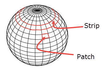
Number of strips = Number of segments / 2
Number of patches = Number of segments * Number of strips
During the MRT calculations the procedure projects a ‘ray’ from the centre of each sphere through the centre of each ‘patch’ looking for the nearest surface that intersects with this ray (enclosure, component or assembly surface). The temperature of this intersected surface is then assigned to the patch. The MRT is finally calculated by summing the area/temperature contributions for the whole sphere.
After pressing OK on the Calculation options dialog, a progress bar will be displayed indicating that mean radiant temperature (MRT) calculations are in progress, followed by another progress bar for the comfort calculations themselves.
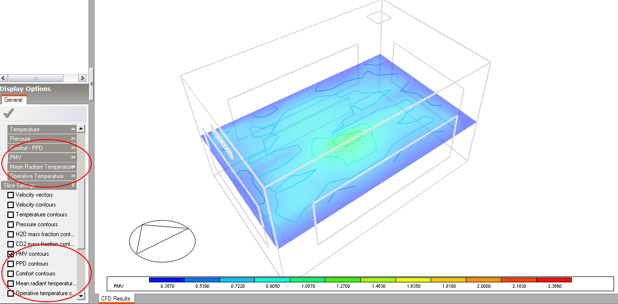
After the comfort calculations have completed additional comfort data will become available and corresponding comfort slice display variables are available on the Display options data panel:
You can find out more about Fanger comfort calculations in the EnergyPlus Thermal Comfort section.