![]() ZoneHVAC:PackagedTerminalHeatPump
ZoneHVAC:PackagedTerminalHeatPump
Used in:
HVAC Zones
|
|
|
Used in:
HVAC Zones |
The packaged terminal heat pump (PTHP) is a compound object made up of other components. Each PTHP consists of these fixed components:
Default settings are assigned to these components at the point the PTHP is created and these can be overridden by editing the individual component properties.
The layout is illustrated below.
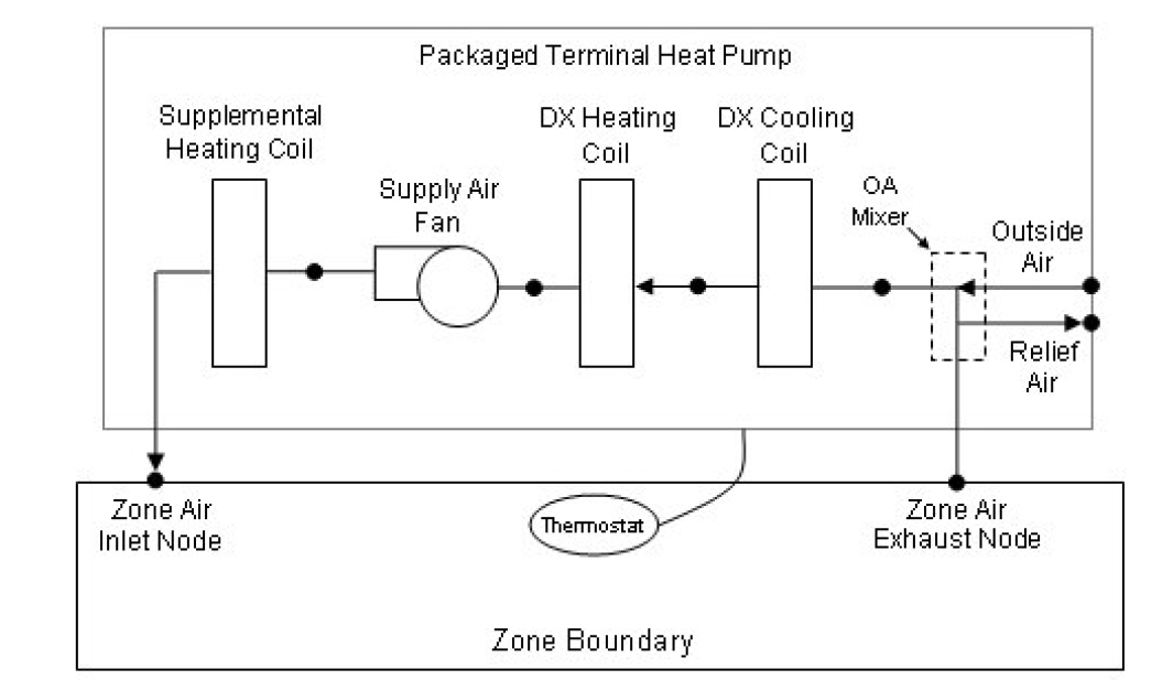
Schematic of a packaged terminal heat pump (draw through fan placement)
The packaged terminal heat pump coordinates the operation of these components and is modelled as a type of zone equipment.
Note: The details of the DX cooling system including compressor, condenser, CoP, part-load performance etc are entered on the DX cooling coil dialog.
The data that must be entered for the PTHP is as follows.
A unique system-assigned name for an instance of a packaged terminal heat pump. Any reference to this heat pump by another object will use this name.
A constant volume fan component is included as a component of the PTHP. Note that the fan’s maximum flow rate should be greater than or equal to the maximum supply air flow rate for the PTHP.
There are 2 fan placement options:
This data specifies the supply air fan operating mode schedule. The supply air fan operating mode may vary during the simulation based on time-of-day or with a change of season. Schedule values of 0 denote that the supply air fan and the heating or cooling coil cycle on and off together to meet the heating or cooling load (a.k.a. AUTO fan). Schedule values other than 0 denote that the supply fan runs continuously while the heating or cooling coil cycles to meet the load.
The default schedule is On with a constant value of 1, i.e. that the supply fan runs continuously while the heating or cooling coil cycles to meet the load at all times. To obtain the AUTO fan configuration select the Off schedule which has a constant value of 0.
To set up a time-varying fan operation mode, create and select a schedule with values of 0 and 1 to define the way the fan operation mode varies in time.
This numeric field defines the supply air flow rate leaving the heat pump (in m3/s or ft3/min) when the DX cooling coil is operating. Values must be greater than 0 or this field is autosizable.
This numeric field defines the supply air flow rate leaving the heat pump (in m3/s or ft3/min) when the DX heating coil and/or supplemental heater are operating. Values must be greater than 0 or this field is autosizable.
This numeric field defines the supply air flow rate leaving the heat pump (in m3/s or ft3/min) when neither cooling or heating is required (i.e., DX coils and supplemental heater are off but the supply air fan operates). This field is only used when the heat pump’s supply air fan operating mode schedule specifies continuous fan operation. Values must be greater than or equal to zero, or this field is autosizable.
If the heat pump’s supply air fan operating mode schedule specifies continuous fan operation and this value is set to zero, then the model assumes that the supply air flow rate when no cooling/heating is needed is equal to the supply air flow rate when the cooling or heating coil was last operating (for cooling operation or heating operation).
If the PTAC provides outdoor air then check this option.
This numeric field defines the outdoor air flow rate through the heat pump (in m3/s or ft3/min) when the DX cooling coil is operating. Values must be greater than or equal to 0, or this field is autosizable.
Note that the outdoor air flow rate during cooling operation is fixed; it cannot change during the simulation. In addition, the outdoor air flow rate during cooling operation cannot be greater than the heat pump’s supply air volumetric flow rate during cooling operation.
This numeric field defines the outdoor air flow rate through the heat pump (in m3/s or ft3/min) when the DX heating coil and/or supplemental heater are operating. Values must be greater than or equal to 0, or this field is autosizable.
Note that the outdoor air flow rate during heating operation is fixed; it cannot change during the simulation. In addition, the outdoor air flow rate during heating operation cannot be greater than the heat pump’s supply air volumetric flow rate during heating operation.
This numeric field defines the outdoor air flow rate through the heat pump (in m3/s or ft3/min) when neither cooling or heating is required (i.e., DX coils and supplemental heater are off but the supply air fan operates). Values must be greater than or equal to 0, or this field is autosizable.
Note that the outdoor air flow rate when no cooling/heating is needed is fixed; it cannot change during the simulation. In addition, the outdoor air flow rate when no cooling/heating is needed cannot be greater than the heat pump’s supply air volumetric flow rate when no cooling/heating is needed. This field is only used when the heat pump’s supply air fan operating mode schedule specifies continuous fan operation. If the heat pump’s supply air fan operating mode schedule specifies continuous fan operation and the field ‘Supply air volumetric flow rate when no cooling or heating is needed’ is set to zero or is left blank, then the model assumes that the outdoor air flow rate when no cooling/heating is needed is equal to the outdoor air flow rate when the cooling or heating coil was last operating (for cooling operation [i.e., Outdoor air flow rate during cooling operation] or heating operation [i.e., Outdoor air flow rate during heating operation]) and this field is not used.
This numeric field defines the minimum outdoor dry-bulb temperature (in °C or °F)elsius for PTHP compressor operation. The compressor will not operate (for DX heating or DX cooling) when outdoor dry-bulb temperatures fall below this value. The minimum value must be greater than or equal to -20°C. The default value is -8°C. This temperature should match the minimum compressor operating temperature specified for the heat pump’s DX heating coil (if they don’t match, the highest of the two temperatures will be the cut-off temperature for compressor operation).
The supplemental heating coil used by this PTHP is fixed as Electric. The supplemental heating coil default settings can be overridden by editing the coil properties.
This numeric field defines the maximum supply air temperature (in °C or °F) exiting the heat pump supplemental heater coil. The supplemental heater will be controlled so that its supply air temperature does not exceed this value. This field is autosizable.
This numeric field defines the maximum outdoor dry-bulb temperature (in °C or °F) for PTHP supplemental heater operation. The supplemental heater will not operate when the outdoor dry-bulb temperature is above this value. The maximum value must be less than or equal to 21°C. The default value is 21°C.
Select the Schedule that defines whether the heat pump operates during a given time period. A schedule value equal to 0 denotes that the heat pump must be off for that time period. A value greater than 0 denotes that the heat pump is available to operate during that time period. This schedule may be used to completely disable the heat pump (all of its coils and the supply air fan) as required.
This numeric field defines the convergence tolerance for the unit’s cooling output. This field allows the user some control over how closely the heat pump will control the air-side conditions. The relative size of this parameter relates directly to the closeness of the control. A very small value in this field will result in tight control and will probably result in larger numbers of iterations. A large value in this field will result in looser controls and could result in unsatisfactory fluctuations in zone air temperature. Initial experience with this parameter lends to the recommendation of using 0.001 as the starting point.
The heat pump is controlled by matching its sensible (temperature) cooling output to the zone sensible load (demand). Because the performance of the DX cooling coil is frequently nonlinear, the heat pump model must call the DX cooling coil model several times (iterate) to determine the proper run time fraction to meet the zone load. The cooling convergence tolerance is the error tolerance used to terminate the iteration procedure when the following equation is satisfied:
( Qzone load - Qheat pump out ) / Qzone load <= Cooling Convergence Tolerance
The maximum number of iterations is limited, with a warning message generated if the above equation is not satisfied within the maximum number of iterations.
This numeric field defines the convergence tolerance for the unit’s heating output. This field allows the user some control over how closely the heat pump will control the air-side conditions. The relative size of this parameter relates directly to the closeness of the control. A very small value in this field will result in tight control and will probably result in larger numbers of iterations. A large value in this field will result in looser controls and could result in unsatisfactory fluctuations in zone air temperature. Initial experience with this parameter lends to the recommendation of using 0.001 as the starting point.
The heat pump is controlled by matching its sensible (temperature) heating output to the zone sensible load (demand). Because the performance of the DX heating coil is frequently non-linear, the heat pump model must call the DX heating coil model several times (iterate) to determine the proper run time fraction to meet the zone load. The heating convergence tolerance is the error tolerance used to terminate the iteration procedure when the following equation is satisfied:
( Qzone load - Qheat pump out) / Qzone load <= Heating Convergence Tolerance
The maximum number of iterations is limited, with a warning message generated if the above equation is not satisfied within the maximum number of iterations.
HVAC,Average,Packaged Terminal Heat Pump Total Zone Heating Rate[W]
HVAC,Sum,Packaged Terminal Heat Pump Total Zone Heating Energy[J]
HVAC,Average,Packaged Terminal Heat Pump Total Zone Cooling Rate[W]
HVAC,Sum,Packaged Terminal Heat Pump Total Zone Cooling Energy[J]
HVAC,Average,Packaged Terminal Heat Pump Sensible Zone Heating Rate[W]
HVAC,Sum,Packaged Terminal Heat Pump Sensible Zone Heating Energy[J]
HVAC,Average,Packaged Terminal Heat Pump Sensible Zone Cooling Rate[W]
HVAC,Sum,Packaged Terminal Heat Pump Sensible Zone Cooling Energy[J]
HVAC,Average,Packaged Terminal Heat Pump Latent Zone Heating Rate[W]
HVAC,Sum,Packaged Terminal Heat Pump Latent Zone Heating Energy[J]
HVAC,Average,Packaged Terminal Heat Pump Latent Zone Cooling Rate[W]
HVAC,Sum,Packaged Terminal Heat Pump Latent Zone Cooling Energy[J]
HVAC,Average,Packaged Terminal Heat Pump Electric Power[W]
HVAC,Sum,Packaged Terminal Heat Pump Electric Consumption[J]
HVAC,Average,Packaged Terminal Heat Pump Fan Part-Load Ratio
HVAC,Average,Packaged Terminal Heat Pump Compressor Part-Load Ratio
This output field is the total (enthalpy) heat addition rate of the packaged terminal heat pump to the zone it is serving in Watts. This value is calculated using the enthalpy difference of the heat pump outlet air and inlet air streams, and the air mass flow rate through the heat pump. This value is calculated for each HVAC system timestep being simulated, and the results (enthalpy addition only) are averaged for the timestep being reported.
This output field is the total (enthalpy) heat addition of the packaged terminal heat pump to the zone it is serving in Joules over the timestep being reported. This value is calculated using the enthalpy difference of the heat pump outlet air and inlet air streams, the air mass flow rate through the heat pump, and the HVAC simulation timestep. This value is calculated for each HVAC system timestep being simulated, and the results (enthalpy addition only) are summed for the timestep being reported.
This output field is the total (enthalpy) heat extraction rate of the packaged terminal heat pump from the zone it is serving in Watts. This value is calculated using the enthalpy difference of the heat pump outlet air and inlet air streams, and the air mass flow rate through the heat pump. This value is calculated for each HVAC system timestep being simulated, and the results (enthalpy extraction only) are averaged for the timestep being reported.
This output field is the total (enthalpy) heat extraction of the packaged terminal heat pump from the zone it is serving in Joules over the timestep being reported. This value is calculated using the enthalpy difference of the heat pump outlet air and inlet air streams, the air mass flow rate through the heat pump, and the HVAC simulation timestep. This value is calculated for each HVAC system timestep being simulated, and the results (enthalpy extraction only) are summed for the timestep being reported.
This output field is the sensible heat addition rate of the packaged terminal heat pump to the zone it is serving in Watts. This value is calculated using the enthalpy difference of the heat pump outlet air and inlet air streams at a constant humidity ratio, and the air mass flow rate through the heat pump. This value is calculated for each HVAC system timestep being simulated, and the results (heating only) are averaged for the timestep being reported.
This output field is the sensible heat addition of the packaged terminal heat pump to the zone it is serving in Joules over the timestep being reported. This value is calculated using the enthalpy difference of the heat pump outlet air and inlet air streams at a constant humidity ratio, the air mass flow rate through the heat pump, and the HVAC simulation timestep. This value is calculated for each HVAC system timestep being simulated, and the results (heating only) are summed for the timestep being reported.
This output field reports the moist air sensible heat extraction rate of the packaged terminal heat pump from the zone it is serving in Watts. This value is calculated using the enthalpy difference of the heat pump outlet air and inlet air streams at a constant humidity ratio, and the air mass flow rate through the heat pump. This value is calculated for each HVAC system timestep being simulated, and the results (cooling only) are averaged for the timestep being reported.
This output field reports the moist air sensible heat extraction of the packaged terminal heat pump from the zone it is serving in Joules over the timestep being reported. This value is calculated using the enthalpy difference of the heat pump outlet air and inlet air streams at a constant humidity ratio, the air mass flow rate through the heat pump, and the HVAC simulation timestep. This value is calculated for each HVAC system timestep being simulated, and the results (cooling only) are summed for the timestep being reported.
This output field is the latent heat addition (humidification) rate of the packaged terminal heat pump to the zone it is serving in Watts. This value is calculated as the difference between the total energy rate and the sensible energy rate provided by the packaged terminal heat pump. This value is calculated for each HVAC system timestep being simulated, and the results (latent heat addition only) are averaged for the timestep being reported.
This output field is the latent heat addition (humidification) of the packaged terminal heat pump to the zone it is serving in Joules over the timestep being reported. This value is calculated as the difference between the total energy delivered to the zone and the sensible energy delivered to the zone by the packaged terminal heat pump. This value is calculated for each HVAC system timestep being simulated, and the results (latent heat addition only) are summed for the timestep being reported.
This output field is the latent heat extraction (dehumidification) rate of the packaged terminal heat pump from the zone it is serving in Watts. This value is calculated as the difference between the total energy rate and the sensible energy rate provided by the packaged terminal heat pump. This value is calculated for each HVAC system timestep being simulated, and the results (latent heat extraction only) are averaged for the timestep being reported.
This output field is the latent heat extraction (dehumidification) of the packaged terminal heat pump from the zone it is serving in Joules over the timestep being reported. This value is calculated as the difference between the total energy delivered to the zone and the sensible energy delivered to the zone by the packaged terminal heat pump. This value is calculated for each HVAC system timestep being simulated, and the results (latent heat extraction only) are summed for the timestep being reported.
This output field is the electricity consumption rate of the packaged terminal heat pump in Watts. The consumption includes electricity used by the compressor (including crankcase heater), fans (indoor supply air fan and the condenser fan), and the supplemental heating coil (if electric). This value is calculated for each HVAC system timestep being simulated, and the results are averaged for the timestep being reported.
This output field is the electricity consumption of the packaged terminal heat pump in Joules for the time period being reported. The consumption includes electricity used by the compressor (including crankcase heater), fans (indoor supply air fan and the condenser fan), and the supplemental heating coil (if electric). This value is calculated for each HVAC system timestep being simulated, and the results are summed for the timestep being reported.
This output field is the part-load ratio of the fan. The fan part-load ratio is defined as the average supply air mass flow rate divided by the maximum supply air mass flow rate. The maximum supply air mass flow rate depends on whether heating, cooling, or no heating or cooling is required during the timestep. This value is calculated for each HVAC system timestep being simulated, and the results are averaged for the timestep being reported.
This output field is the part-load ratio of the compressor used by the DX coils (cooling and heating). Compressor part-load ratio is defined as the total coil load divided by the coil steady-state capacity. This value is calculated for each HVAC system timestep being simulated, and the results are averaged for the timestep being reported.