![]() ZoneHVAC:TerminalUnit:VariableRefrigerantFlow
ZoneHVAC:TerminalUnit:VariableRefrigerantFlow
Used in:
HVAC Zones
|
|
|
Used in:
HVAC Zones |
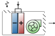
VRF Indoor units with variable refrigerant flow DX coils are used exclusively with variable refrigerant flow (VRF) systems. Indoor units operate to satisfy a heating or cooling load in a zone based on a zone thermostat temperature set point. Direct-expansion (DX) cooling and DX heating coils are specified and used depending on the operating mode required. Although a DX cooling and a DX heating coil are included in the terminal unit, only one may be used at any one time.
Outdoor ventilation air is modelled with the use of an optional outside air mixer object. Outside air can be provided to the zone in one of two ways: either only when the coil is operating, or continuously even when the coil is not operating. A supply air fan is also included and it can be modelled as either draw through or blow through.
The zone terminal unit will typically be the first equipment operating for both cooling and heating (i.e., Sequence = 1 on the Heating and Cooling Calculation Sequence tab of the HVAC zone group dialog). Other Zone HVAC equipment may be used in the same zone and should be sequenced to operate after the zone terminal units (i.e., sequence = 2 or higher).
The name of the VRF indoor unit is defined internally and cannot be changed.
Select the schedule that defines when the terminal unit is able to operate. A schedule value equal to 0 means that the unit is off at that time and a value greater than 0 denotes that it is available to operate. This schedule may be used to completely disable the unit as required.
This numeric field defines the terminal unit’s operating volumetric air flow rate (in m3/s or ft3/min). This volumetric air flow rate is used when the terminal unit is operating in cooling mode.
This numeric field defines the terminal unit’s operating volumetric air flow rate (in m3/s or ft3/min). This volumetric air flow rate is used when the terminal unit is operating in heating mode.
This numeric field defines the terminal unit’s operating volumetric air flow rate (in m3/s or ft3/min). This volumetric air flow rate is used when the terminal unit’s cooling coil is not operating and the previous mode was cooling.
This numeric field defines the terminal unit’s operating volumetric air flow rate (in m3/s or ft3/min). This volumetric air flow rate is used when the terminal unit’s heating coil is not operating and the previous mode was heating.
Check this checkbox if the VRF indoor unit has its own supply of fresh air. Then enter the 3 flow rates described below.
This autosizable field defines the outdoor air volumetric air flow rate (in m3/s or ft3/min). This volumetric air flow rate is used when the terminal unit is operating in cooling mode.
This autosizable field defines the outdoor air volumetric air flow rate i(in m3/s or ft3/min). This volumetric air flow rate is used when the terminal unit is operating in heating mode.
This autosizable field defines the outdoor air volumetric air flow rate (in m3/s or ft3/min). This volumetric air flow rate is used when the terminal unit is not operating in cooling or heating mode.
This numeric field defines the parasitic electrical energy use of the zone terminal unit when either terminal unit coil is operating. When in cooling mode, this electric energy use is reported in a zone terminal unit cooling electric consumption output variable. When in heating mode, this electric energy use is reported in a zone terminal unit heating electric consumption output variable. Units are W or Btu/hr.
This numeric field defines the parasitic electrical energy use of the zone terminal unit when the terminal unit coil(s) is not operating. When the previous mode was cooling, this electric energy use is reported in a zone terminal unit cooling electric consumption output variable. When the previous mode was heating, this electric energy use is reported in a zone terminal unit heating electric consumption output variable. Units are W or Btu/hr.
This choice field contains the identifying type of supply air fan specified for the indoor unit. Fan type must be one of:
This option has two choices:
Schedule values equal to 0 denote cycling fan/cycling coil operation. All other schedule values denote constant fan/cycling coil operation.
Check this option if you would like to override the Rated total heating capacity sizing ratio used for the Outdoor unit.
This field defines the ratio of the heating coil to cooling coil size when DX heating coil capacity is autosized. It must be greater than or equal to 1. The default value is 1.