Note on terminology: The terms VRF "condenser", "outdoor unit" and "heat pump" are used interchangeably in the this section. Likewise the terms VRF indoor unit and terminal unit are used interchangeably.
Enter the name of the VRF outdoor unit.
To load a pre-configured VRF outdoor unit dataset, select a template from the list.
This field determines the type of fuel that this variable refrigerant flow system uses. This field has seven choices:
The default is 2-Electricity. The use of alternate fuel types assumes an engine drives the variable speed compression system and also accounts for condenser air flow (i.e., a fan attached to the engine provides air flow through the outdoor condenser.
This numeric field specifies the minimum operating part-load ratio (PLR) of the heat pump. When the heat pump operates at a PLR below this value, the heat pump’s compressor will cycle to meet the cooling or heating demand. Above this value, the heat pump’s compressor operates the entire time step to meet the cooling or heating demand. The minimum value for this field is 0. If this field is left blank, the default value is 0.15. When the heat pump compressor cycles, the heating part-load fraction correlation curve is used to determine cycling losses.
Select the schedule that defines when the heat pump operates during a given time period. A schedule value equal to 0 denotes that the heat pump must be off for that time period. A value other than 0 denotes that the heat pump is available to operate during that time period. This schedule may be used to completely disable the heat pump (and all of its terminal units) as required.
This selection determines the logic used to simulate the “master” thermostat. Valid choices are:
When the master thermostat priority control type is set to 3-Thermostat offset priority, or 4-Master thermostat priority you must select the zone where the “master” thermostat is located. When the heat pump is connected to multiple zone terminal units, one terminal unit must be selected as the master thermostat. The remaining thermostats are slaves and can operate only in the same mode as the master thermostat.
When the master thermostat priority control type is set to 5-Scheduled the schedule must be selected. Schedule values of 0 denote cooling mode while values of 1 denote heating mode. Any other values will force the system off.
This field defines the equivalent pipe length (in m or ft) between the farthest terminal unit and the heat pump condenser. It includes the gas refrigerant line length (for both horizontal and vertical distances), fitting losses, pipe bends, and other connections that contribute to piping losses. This field is used to calculate the piping correction factor in cooling mode. It defines the head losses due to the pipe length between the farthest terminal unit and the heat pump condenser and impacts the maximum available capacity in cooling mode.
This field defines the vertical pipe height (in m or ft) between the highest or lowest terminal unit and the heat pump condenser. It defines the gravitational losses due to a change in height between the highest (positive value), or lowest (negative value) terminal unit and the heat pump condenser. The distance specified here is applied to the piping correction factor calculation for both cooling and heating. If the distance between the highest terminal unit above the heat pump condenser is greater than the distance between the lowest terminal unit below the condenser enter the difference between the highest and lowest terminal units as a positive distance, otherwise enter this difference as a negative distance.
For example, if the distance from the heat pump condenser to the highest terminal unit above the condenser is 10 m and the distance from the heat pump condenser to the lowest terminal unit below the condenser is -15 m, then enter a value of -5 m in this field. This head loss impacts the maximum available capacity in cooling mode.
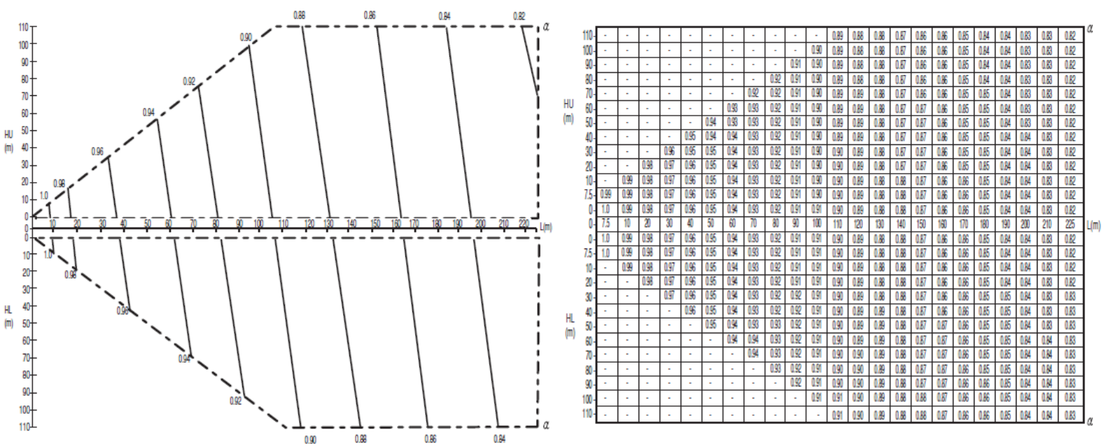
Manufacturers may provide information for how the piping losses change with height of the VRF indoor unit with respect to the outdoor unit. The piping correction factor for height in cooling mode can be calculated as a quotient of correction factor decrease to unit height difference (in SI units) with a correct sign, i.e. correction factor decreases (more losses) as height increases.
The figure below from a manufacturer provides this information in the tilted vertical lines on the chart, which shows that the correction factor decreases by about 0.11 when the terminal unit is 110 m above the condenser. This means that the correction factor for height is -0.11 / 110 m or -0.001.
Example manufacturers data
This field defines the equivalent pipe length (in m or ft) between the farthest terminal unit and the heat pump condenser. It includes the liquid refrigerant line length (for both horizontal and vertical distances), fitting losses, pipe bends, and other connections that contribute to piping losses. This field is used to calculate the piping correction factor in heating mode. It defines the head losses due to the pipe length between the farthest terminal unit and the heat pump condenser and impacts the maximum available capacity in heating mode.
See help above for Equivalent piping length used for piping correction factor in cooling mode
This field defines the linear, quadratic, or cubic curve used to calculate the piping correction factor for length in cooling mode. Piping losses are a function of piping length. If sufficient piping loss information is available where piping losses are also a function of combination ratio (i.e., in addition to length), a biquadratic performance curve may be used.
This field defines the linear, quadratic, or cubic curve used to calculate the piping correction factor for length in heating mode. Piping losses are a function of piping length. If sufficient piping loss information is available where piping losses are also a function of combination ratio (i.e., in addition to length), a biquadratic performance curve may be used.
This numeric field defines the electrical power consumed by the crankcase heater (in W or Btu/h) for each compressor. This crankcase heater power is consumed when the outdoor temperature is below the maximum outdoor dry-bulb temperature for crankcase heater operation. The minimum value for this field is 0. Crankcase heater electrical consumption is applied only when the compressor is off or is applied during the off cycle when the compressor is cycling below the Minimum heat pump part-load ratio. This field is only used to calculate crankcase heater power and has no impact on heat pump performance.
This field defines the number of compressors in the heat pump condensing unit and is used exclusively to determine the operating characteristics of the crankcase heater. For example, if the number of compressors is 3, one crankcase heater will operate when the heat pump condensing unit’s part-load ratio is less than or equal to 0.67 (when the ratio of compressor size to total compressor capacity input is 0.33) and the outdoor temperature is below the maximum outdoor temperature for crankcase heater operation. Similarly, two crankcase heaters will operate when the heat pump condensing unit’s PLR is less than or equal to 0.33 and the outdoor temperature is below the maximum outdoor temperature for crankcase heater operation. If the heat pump condensing unit is off, all 3 crankcase heaters will operate if the outdoor temperature is below the maximum outdoor temperature for crankcase heater operation. The minimum value for this field is 1. This field is only used to calculate crankcase heater power and has no impact on heat pump performance.
This field defines the size of the first stage compressor to the total compressor capacity and is used exclusively for calculating crankcase heater energy. When the number of compressors is greater than 2, the 2nd stage compressor and all additional compressors are assumed to be equally sized. This field is only used to calculate crankcase heater power and has no impact on heat pump performance.
This field defines the maximum outdoor temperature, (in °C or °F), below which the crankcase heater will operate. This field is only used to calculate crankcase heater power and has no impact on heat pump performance.
This alpha field has two choices:
Defrost can be disabled by entering a resistive defrost strategy using a timed defrost control, a 0 defrost time period fraction and a 0 resistive defrost heater capacity in the following inputs fields. This method is used when the Maximum outdoor dry-bulb temperature for defrost operation value is greater than the expected minimum outdoor dry-bulb temperature simulated in the weather file.
This field has two choices:
Regardless of which defrost control is selected, defrost does not occur above the user specified outdoor temperature entered in the Maximum outdoor dry-bulb temperature for defrost operation.
Available only when the reverse-cycle defrost strategy option is selected, this field defines the name of a bi-quadratic performance curve that parameterizes the variation of the energy input ratio (EIR) during reverse-cycle defrost periods as a function of the outdoor air dry-bulb temperature and the weighted average wet-bulb temperature of the air entering the indoor terminal units. The output of this curve is multiplied by the coil capacity, the fractional defrost time period and the runtime fraction of the heating coil to give the defrost power at the specific temperatures at which the indoor and outdoor coils are operating. The curve is normalized to a value of 1.0 at the rating point conditions.
This field defines the fraction of compressor runtime when the defrost cycle is active. For example, if the defrost cycle is active for 3.5 minutes for every 60 minutes of compressor runtime, then the user should enter 3.5/60 = 0.058333. The value for this input field must be greater than or equal to 0. If this input field is left blank, the default value is 0.058333.
This field defines the capacity of the resistive defrost heating element (in W or Btu/h). It is available only when the selected defrost strategy is 1-Resistive. The value for this input field must be greater than or equal to 0.
This field defines the outdoor air dry-bulb temperature (in °C or °F) above which outdoor coil defrosting is disabled. Defrost can be completely eliminated by selecting a temperature lower than the minimum expected outdoor temperature found in the weather file.
This choice field defines the configuration of the heat pump condenser. Valid choices are:
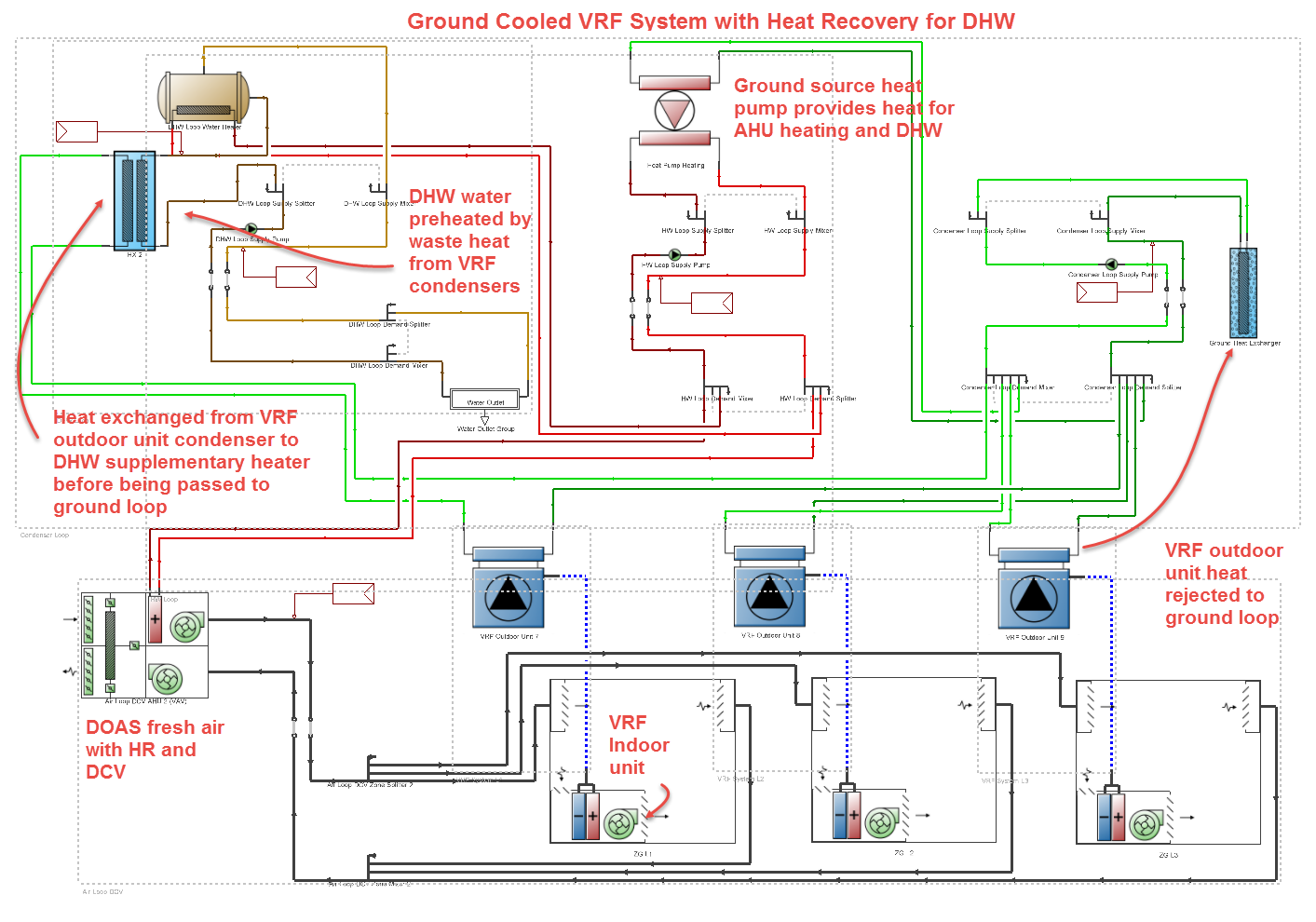
Example of VRF system where waste heat is recovered from water-cooled outdoor unit for preheating DHW
For details on evaporatively cooled systems see below under Evaporative condenser effectiveness.
This autosizable numeric field defines the condenser water volume flow rate (in m3/s or gal/min) and is only available for water-cooled systems.
The effectiveness of the evaporative condenser, which is used to determine the temperature of the air entering the outdoor condenser coil as follows:
Tcond inlet = Twbo + (1 - EvapCondEffectiveness) (Tdbo - Twbo)
where:
Tcond inlet = the temperature of the air entering the condenser coil (°C)
Twbo = the wet-bulb temperature of the outdoor air (°C)
Tdbo = the dry-bulb temperature of the outdoor air (°C)
The resulting condenser inlet air temperature is used by the Cooling capacity ratio modifier function of temperature curve and the Cooling energy input ratio (EIR) modifier function of temperature curve. The default value for this field is 0.9, although valid entries can range from 0.0 to 1.0.
To model an air cooled condenser specify Condenser type = 1-Air cooled. In this case the Cooling capacity ratio modifier function of temperature curve and the Cooling energy input ratio (EIR) modifier function of temperature curve should be defined as a function of outdoor dry-bulb temperature.
To model an evaporative-cooled condenser where you have performance curves that are a function of the wet-bulb temperature of air entering the condenser coil, then you should specify Condenser type = 2-Evaporatively cooled. In this case the evaporative condenser effectiveness value should be entered as 1.0 and the Cooling capacity ratio modifier function of temperature curve and the Cooling energy input ratio (EIR) modifier function of temperature curve should both be defined as a function of the wet-bulb temperature of air entering the condenser coil.
To model an air-cooled condenser that has evaporative media placed in front of it to cool the air entering the condenser coil, specify Condenser type = 2-Evaporatively cooled and enter the appropriate evaporative effectiveness for the media. In this case, the Cooling capacity ratio modifier function of temperature curve and the Cooling energy input ratio (EIR) modifier function of temperature curve should both be defined as function of outdoor dry-bulb temperature. Be aware that the evaporative media will significantly reduce the dry-bulb temperature of the air entering the condenser coil, so the Cooling Capacity and Cooling EIR Modifier Curves must be valid for the expected range of dry-bulb temperatures that will be entering the condenser coil.
The air volume flow rate (in m3/s or ft3/min) entering the evaporative condenser. This value is used to calculate the amount of water used to evaporatively cool the condenser inlet air. The minimum value for this field must be greater than zero, and this input field is autosizable (equivalent to 0.000144 m3/s per watt of Gross rated total cooling capacity [850 cfm/ton]). This field is not used when Condenser type = 1-Air cooled.
The rated power of the evaporative condenser water pump (in W or Btu/h). This value is used to calculate the power required to pump the water used to evaporatively cool the condenser inlet air. The default value for this input field is zero, but it is autosizable (equivalent to 0.004266 W per watt [15 W/ton] of Gross rated total cooling capacity). This field is not used when Condenser type = 1-Air cooled.
This field contains the capacity of the heat pump’s electric basin heater (in W/K or Btu/h). This field only applies for Condenser type = 2-Evaporatively cooled. This field is used in conjunction with the Basin heater setpoint temperature described below. The basin heater electric power is equal to this field multiplied by the difference between the basin heater set point temperature and the outdoor dry-bulb temperature. The basin heater only operates when the heat pump compressor(s) is off, regardless of the basin heater schedule described below. The basin heater capacity must be greater than or equal to zero.
This field contains the set point temperature (˚C or ˚F) for the basin heater described above. This field only applies for Condenser type = 2-Evaporatively cooled. The basin heater is active when the outdoor air dry-bulb temperature falls below this setpoint temperature, as long as the heat pump is off. This set point temperature must be greater than or equal to 2˚C.
Select the basin heater operating schedule. This field only applies for Condenser type = 2-Evaporatively cooled. The basin heater operating schedule is assumed to be an on/off schedule and the heater is available to operate any time the schedule value is greater than 0. The basin heater operates when scheduled on and the outdoor air dry-bulb temperature is below the set point temperature described above. Regardless of this schedule, the basin heater may only operate when the heat pump is off.