Available in DesignBuilder v5.1 and later only
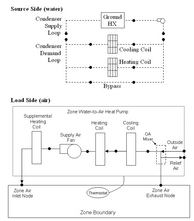
The zone water-to-air heat pump is a compound component consisting of a fan, water-to-air cooling and heating coils, and a supplemental heating coil. The heat pump switches between cooling and heating depending on the zone’s demand. The zone load (air) side of the zone water-to-air heat pump consists of an On/Off fan component, a Water to air heat pump cooling coil component, a Water to air heat pump heating coil component, and a Gas or Electric supplemental heating coil component. The source side (water) of the heat pump is connected to a condenser loop with a heat exchanger (ground heat exchanger or other type) or a plant loop with a heating source such as a boiler and a cooling source such as a chiller or cooling tower.
The diagram below shows the setup and connection of the heat pump for the source side and load side for a ground heat exchanger configuration.
Note that on the load side, the cooling coil is always placed before the heating coil.
A typical whole system configuration within DesignBuilder is shown below:
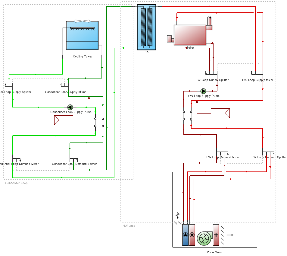
Note the use of a HX component to provide free cooling from a cooling tower from a connected condenser loop to a mixed water loop which can provide either heating or cooling depending on the zone loads. The HW loop was configured with:
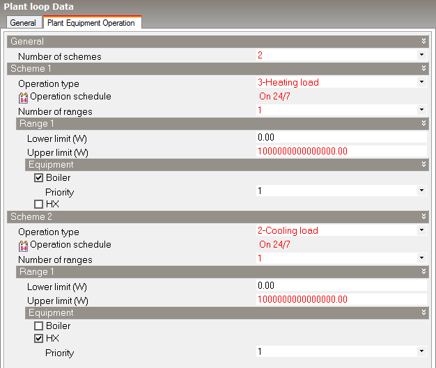
The HX component is controlled using the 1-Cooling differential on/off Control type.
A unique system-assigned name for this zone system heat pump. Any reference to this unit by another object will use this name.
Select the schedule that defines when the heat pump is able to operate. A schedule value equal to 0 means that the heat pump is off at that time and a value greater than 0 denotes that it is available to operate. This schedule may be used to completely disable the heat pump (all of its coils and the supply air fan) as required.
There are 2 options:
This numeric field contains the time delay in seconds for the heat pump supply air fan to shut off after compressor cycle off. This value can be obtained from the manufacturer or the heat pump catalog. Suggested value is 60 seconds.
This numeric field defines the supply air flow rate leaving the heat pump (in m3/s or ft3/s) when the DX cooling coil is operating. Values must be greater than 0 or this field is autosizable.
This numeric field defines the supply air flow rate leaving the heat pump (in m3/s or ft3/s) when the DX heating coil and/or supplemental heater are operating. Values must be greater than 0 or this field is autosizable.
This numeric field defines the supply air flow rate leaving the heat pump (in m3/s or ft3/s) when neither cooling nor heating is required (i.e., DX coils and supplemental heater are off but the supply air fan operates). This field is only used when the heat pump’s supply air fan operating mode schedule specifies continuous fan operation. Values must be greater than or equal to zero, or this field is autosizable. If the heat pump’s supply air fan operating mode schedule specifies continuous fan operation and this value is set to zero, then the model assumes that the supply air flow rate when no cooling/heating is needed is equal to the supply air flow rate when the cooling or heating coil was last operating (for cooling operation or heating operation).
Check this check box if the heat pump unit is to provide outdoor air to the zone.
This numeric field defines the outdoor air flow rate through the heat pump (in m3/s or ft3/s) when the DX cooling coil is operating. Values must be greater than or equal to 0, or this field is autosizable. Note that the outside air flow rate during cooling operation is fixed; it cannot change during the simulation. In addition, the outside air flow rate during cooling operation cannot be greater than the heat pump’s supply air flow rate during cooling operation.
This numeric field defines the outdoor air flow rate through the heat pump (in m3/s or ft3/s) when the DX heating coil and/or supplemental heater are operating. Values must be greater than or equal to 0, or this field is autosizable. Note that the outside air flow rate during heating operation is fixed; it cannot change during the simulation. In addition, the outside air flow rate during heating operation cannot be greater than the heat pump’s supply air flow rate during heating operation.
This numeric field defines the outdoor air flow rate through the heat pump (in m3/s or ft3/s) when neither cooling or heating is required (i.e., DX coils and supplemental heater are off but the supply air fan operates). Values must be greater than or equal to 0, or this field is autosizable. Note that the no load outdoor air flow rate cannot change during the simulation. In addition, the no load outdoor air flow rate cannot be greater than the heat pump’s no load supply air flow rate. This field is only used when the heat pump’s supply air fan operating mode schedule specifies continuous fan operation. If the heat pump’s supply air fan operating mode schedule specifies continuous fan operation and the field Supply air flow rate when no heating or cooling needed set to zero, then the model assumes that the no load outdoor air flow rate is equal to the outdoor air flow rate when the cooling or heating coil was last operating (for cooling operation [i.e., Cooling outdoor air flow rate] or heating operation [i.e., Heating outdoor air flow rate]) and this field is not used.
This numeric field contains the fraction of on-cycle power use to adjust the part load fraction based on the off-cycle power consumption due to crankcase heaters, controls, fans, and etc. Suggested value values are below (Henderson et al. 1999):
| Heat Pump Condition | Recommended Values |
| Typical | 0.01 |
| Good | 0.01 |
| Poor | 0.03 |
This numeric field contains the time constant for the cooling coil’s capacity to reach steady state after startup. Suggested values are shown below (Henderson et al. 1999):
| Heat Pump Condition | Recommended Values |
| Typical | 60 |
| Good | 60 |
| Poor | 60 |
This numeric field contains the maximum on-off cycling rate for the compressor, which occurs at 50% run time fraction. Suggested values are shown below (Henderson et al. 1999):
| Heat Pump Condition | Recommended Values |
| Typical | 2.5 |
| Good | 2.5 |
| Poor | 3.0 |
This numeric field defines the maximum allowed supply air temperature exiting the heat pump supplemental heating coil (in °C or °F).
This numeric field defines the outdoor air dry-bulb temperature (in °C or °F) above which the heat pump supplemental heating coil is disabled. The temperature for this input field must be less than or equal to 21°C.
Select the name of the supply air fan operating mode schedule. The supply air fan operating mode may vary during the simulation based on time-of-day or with a change of season. Schedule values of 0 denote that the supply air fan and the heating or cooling coil cycle on and off together to meet the heating or cooling load (a.k.a. AUTO fan). Schedule values other than 0 denote that the supply air fan runs continuously while the heating or cooling coil cycles to meet the load.
Note: This setting is not available yet for selection. DesignBuilder provides a constant value of 1 in the simulation, i.e. the fan will run continuously while the coils cycle to meet the load.
This field specifies the way in which water flow through the heat pump coils will be modelled. There are 3 options:
Note: This field is only used when WatertoAirHeatPump:EquationFit coils are used.