Navigator toolbar icon. This will ensure that the Navigator is synchronised with the model.
DesignBuilder provides a great deal of flexibility in the way that block and zone geometry is defined and passed through to the various calculations. There are various options including building blocks drawn using external measurements while providing correct internal zone geometry for floor area and zone volume calculations derived from actual surface thickness. It is also possible to use a simpler approach where the block and zone dimensions drawn are exactly the ones used in calculations and the thickness of the surfaces are not considered in the analysis.
Select the template which best fits the way you would like to define the building geometry. Templates provided include:
External measurements, internal zone geometry - blocks are defined using external measurements and surfaces dimensions, zone volume and floors areas are all derived from the inner zone geometry.
The usual inheritance mechanism applies so loading the required template at building level defines the geometry convention for the whole building. Settings can be made at building level only but Fixed surface thicknesses can be defined down to surface level and Void depths can be defined down to Zone level.
The Geometry convention template can also selected when creating a new building.
Tip: After making any changes to the model which could affect the geometry including construction type selection as well as the settings described on this page, you should manually refresh the Navigator by pressing the Refresh Navigator toolbar icon. This will ensure that the Navigator is synchronised with the model.
This setting defines whether the geometric surface data used in the calculation (heat transfer etc) is based on the inner or outer zone volume dimensions. Options are:
Note: In cases where the 1-Inner volume option is selected and non-zero surface thickness settings are being used, any component block shading devices placed adjacent to the block at building level will not be exactly adjacent to the corresponding zone inner surfaces used in the simulations which are offset inwards from the block outer geometry. The resultant gap will allow solar radiation to pass into the windows which will not be apparent by looking at the model at building level or on the visualisation screen. You are therefore advised to avoid using the combination of 1-Inner volume geometry, non-zero surface thickness and external component blocks used as local shading devices. This issue does not arise with the local shading mechanism which ensures that overhangs, sidefins and louvre blades are offset with the window.
This setting dictates whether internal or external measurements are used to calculate the zone volume is required to calculate air volumes etc.
Note: Unless otherwise specified by your regional modelling code, the 1-Inner volume setting should generally be used for calculating zone volume.
This setting dictates whether internal or external measurements are used to calculate the zone floor area. The options are:
The floor area calculated from the method selected here is used for:
Note: Unless otherwise specified by your regional modelling code, the 1-Inner volume setting should generally be used for calculating zone floor area.
Tip: For zones with walls that have a finite thickness, this floor area will not be the same as the total area of the floor surfaces listed in the Navigator, whose geometry is based on the Zone geometry and surface areas method.
This setting is used to specify whether or not the outside wall surface or inside wall surface is to used to calculate the available area for glazing. This option is only visible when the Zone geometry and surface areas option is set to 2-Outer. Options are:
When the attribute is set to use the outer wall surface, visualisations will default to single skin display (all walls paper thin) to allow full size windows to be rendered accurately.
Each surface can have its geometric thickness calculated from the construction selected but only when the checkbox for the associated surface type (list below) is unchecked. If the thickness is to be overridden then check the appropriate checkbox and enter the fixed surface thickness. Settings can be made from building level right down to surface level giving considerable flexibility over the model geometry.
In most cases you should simply select the Geometry convention template - you shouldn't normally need to override the surface thickness settings below.
Note: The surface thickness does not affect the thermal properties of the wall/floor/roof etc (U-value, thermal mass etc). Surface thermal properties are based purely on the construction data specified for the surface.
If the external wall surface thickness is to be overridden (i.e. not derived from construction thickness) then check the checkbox and enter the wall thickness (in m or in).
If the below grade wall surface thickness is to be overridden (i.e. not derived from construction thickness) then check the checkbox and enter the wall thickness (in m or in).
If the partition surface thickness is to be overridden (i.e. not derived from construction thickness) then check the checkbox and enter the wall thickness (in m or in).
If the ground floor surface thickness is to be overridden (i.e. not derived from construction thickness) then check the checkbox and enter the floor thickness (in m or in).
Note: In most cases ground floor blocks are measured from ground level and the ground slab construction is not included in the volume of the building so this setting is normally overridden to be zero.
The basement ground floor is the construction used for underground ground floors (i.e. the floor is located at a height lower than z=0). If the basement ground floor surface thickness is to be overridden (i.e. not derived from construction thickness) then check the checkbox and enter the floor thickness (in m or in).
If the external floor surface thickness is to be overridden (i.e. not derived from construction thickness) then check the checkbox and enter the floor thickness (in m or in).
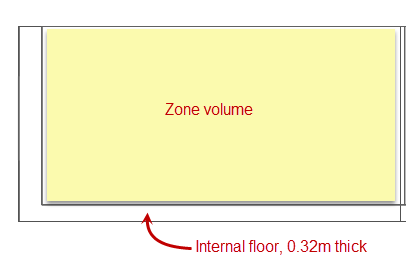
If the internal floor surface thickness is to be overridden (i.e. not derived from construction thickness) then check the checkbox and enter the floor thickness (in m or in).
If the semi-exposed wall surface thickness is to be overridden (i.e. not derived from construction thickness) then check the checkbox and enter the wall thickness (in m or in).
If the semi-exposed floor surface thickness is to be overridden (i.e. not derived from construction thickness) then check the checkbox and enter the floor thickness (in m or in).
If the semi-exposed ceiling surface thickness is to be overridden (i.e. not derived from construction thickness) then check the checkbox and enter the ceiling thickness (in m or in).
If the flat roof surface thickness is to be overridden (i.e. not derived from construction thickness) then check the checkbox and enter the flat roof thickness (in m or in).
If the pitched roof surface thickness is to be overridden (i.e. not derived from construction thickness) then check the checkbox and enter the pitched roof thickness (in m or in).
When running parametric or optimisation studies in which wall or other surface thickness are changed as part of the parametric variations, there can be other significant knock-on impacts on the model geometry including varying floor area (and so internal gains, ventilation etc) and zone volume (and so ventilation and infiltration changes). To avoid running into these issues you can fix surface thickness for the relevant part of the model. For example if wall insulation thickness is being varied in a parametric analysis and you don't wish these changes to impact on zone floor area and volume then you could apply a constant External wall thickness.
Tip: the easiest way to avoid any such issues would be to use the "Simple" Geometry conventions template at the outset.
The depth of the ceiling void (in m or in). This is used, in addition to any surface thickness applied to the ceiling/roof surface to reduce the size of the zone inner volume and surfaces areas to account for the ceiling void.
Note: If the ceiling/roof construction already includes an air gap to define the ceiling void and its thickness is being used to define the inner volume then you should enter 0 here. Likewise, if the ceiling void is already modelled using its own zone then enter 0.
The depth of the floor void (in m or in). This is used, in addition to any surface thickness applied to the floor surface to reduce the size of the zone inner volume and surfaces areas to account for the floor void.
Note: If the floor construction already includes an air gap for the floor void and its thickness is being used to define the inner volume then you should enter 0 here. Likewise, if the floor void is already modelled using its own zone then enter 0.
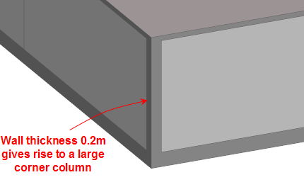
When using 1-Inner Zone geometry and surface areas option, DesignBuilder creates an "inner volume" by moving all zone surfaces inwards using the construction thicknesses (or fixed thicknesses where specified). This process is called "deflation". In some cases, however the deflation process is not possible and the inner volume cannot be generated. The two main reasons for this failure are:
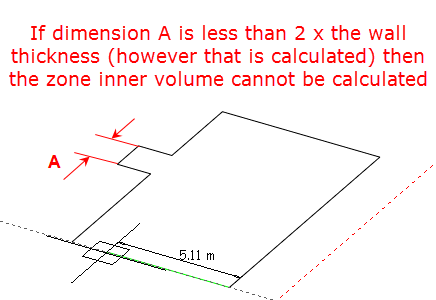
If the deflation process fails, the software uses an alternative mechanism in which the zone outer geometry is used for all zone thermal surfaces. Although DesignBuilder is unable to generate full inner zone geometry for these zones it can still calculate zone inner volumes and floor areas fairly accurately using a simpler algorithm based on the outer zone geometry and surface thicknesses.
Zone inner geometry is calculated zone by zone and so if the deflation process fails for 1 zone in a block, this should not affect the process in other zones in the block.
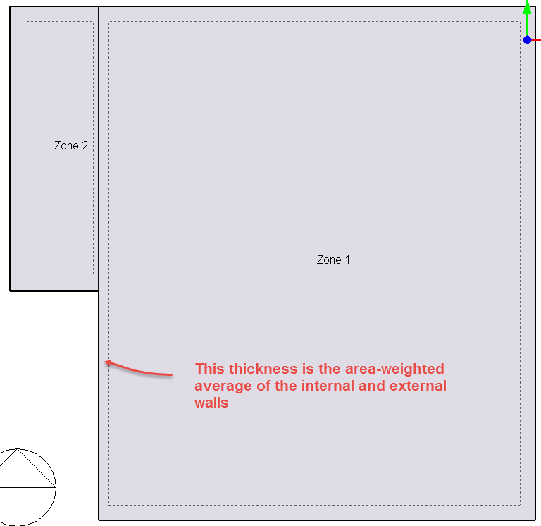
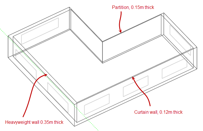
In cases where a surface is made up of more than one adjacency, each using a different construction, DesignBuilder must use an area-weighted average surface thickness. For example:
External measurements, perspective view
External measurements, section view
When modelling continuous glazing for curtain walls, atria, greenhouses etc. it is often necessary to model glazing joining at the corners. It is not possible for windows to literally meet in this way because EnergyPlus requires all openings (windows, doors etc) to be placed on a parent surface with at least a small gap between the opening and the parent surface edge. But by using a low value of wall surface thickness you can give the appearance of adjacent windows as shown below.
A small wall thickness, below, allows the glazing to cover most of the wall giving good results (below).
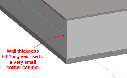
A larger wall thickness, below, requires more area to cater for the walls joining at the corners and the glazing does not meet 'round the corner' giving poor results (below).