Construction tab in model data under Airtightness header
Infiltration is included by default but you can switch infiltration off by unchecking the Model infiltration checkbox. This may be useful if you are carrying out a calculated natural ventilation summertime simulation of a large building to reduce the number of cracks in the model and so speed simulations.
Note: if you switch off infiltration when Calculated natural ventilation is active, you should make sure that the Natural ventilation option on the HVAC tab is switched on to ensure that sufficient flow paths exist. Otherwise EnergyPlus may generate errors.
When Calculated natural ventilation is active, the Airtightness is defined through a crack template. Depending on the Airtightness method model option there are 2 different ways to define the airtightness of the building:
These options are used as follows.
Airtightness is defined through a five point scale:
The five settings correspond to 5 pre-defined Crack templates.
When the 2-Crack template Airtightness method is used, airtightness is defined through a specific selection of a template which can be user-defined. With this method it is still possible to select the pre-defined crack templates referred to by the Template slider method.
When using Calculated natural ventilation there are 2 main categories of uncontrolled infiltration airflow:
The data that allows DesignBuilder to generate these airflow paths is stored in Crack templates. For example, take a 20m2 external wall with a single 2m x 1m window. If the Good crack template is selected for the surface then the flow paths used in the simulations will be as follows:
The screenshots below indicate the source of the above Crack template values.
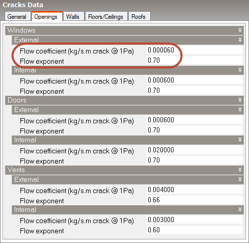
External window crack data in Crack template dialog
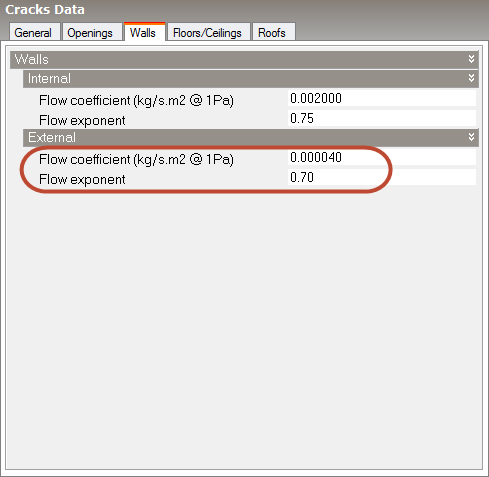
External wall crack data in Crack template dialog
Note: As well as being included in standard simulations, infiltration from Calculated natural ventilation is also included in Detailed HVAC autosizing calculations and also in Simple HVAC sizing when using the 2-EnergyPlus Simple HVAC autosizing method.
Enter the maximum rate of infiltration, which is modified by the multiplier fraction factors in the Schedule select below. The units for the infiltration depend on the Infiltration units Model data setting. This value and the associated schedule below are used for Cooling design calculations as well as simulations when using Scheduled natural ventilation.
Select the schedule which defines any time-varying of the infiltration. The default schedule is On giving a constant infiltration rate based on the Constant rate entered as described above.