Create a building model first then follow the steps below to set up a water to water (ground source) heat pump (GSHP) system using vertical boreholes to provide both heating through heated floors and cooling through chilled beams.
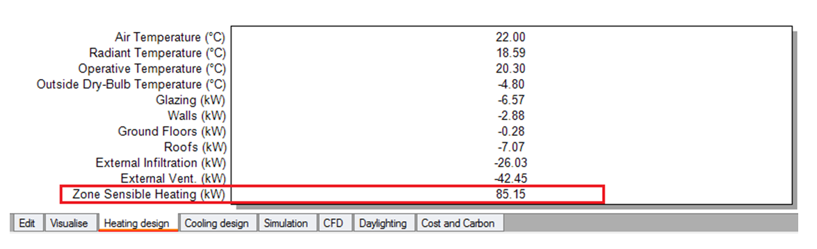
In this case, peak heating load is 85 kW.
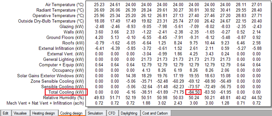
In this case, (coincidently) the peak cooling load is also 85 kW.
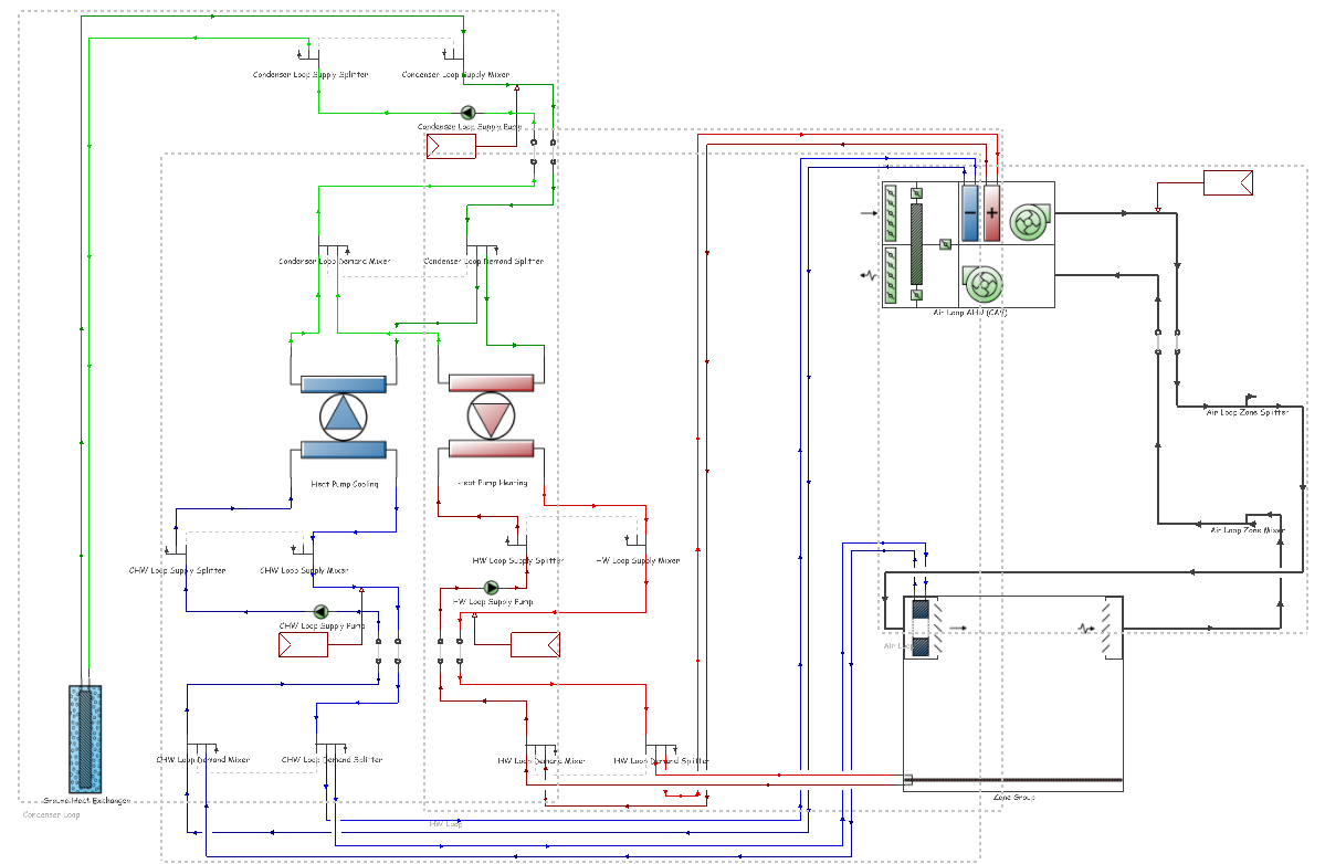
The layout below shows a typical heating and cooling application. This was loaded from the GSHP - Heated Floor and Chilled Beams HVAC template but you can create a similar layout from scratch to suit your particular configuration.
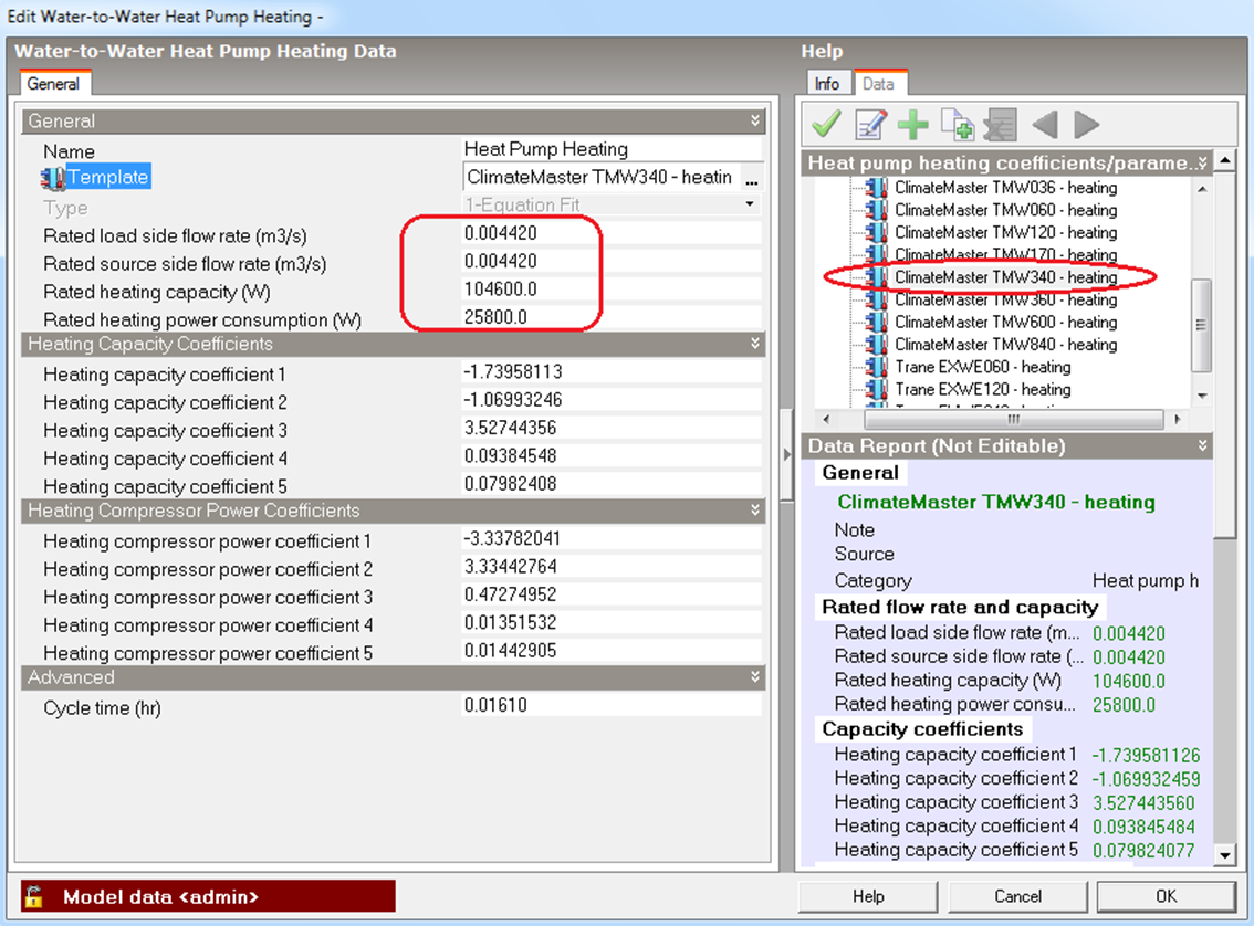
Navigate to the Heat pump heating component and edit it. Load an appropriate heat pump template using the heat pump Rated heating capacity data to match the heat pump with the design heating load calculated in step 1. You can see in the example below a heat pump having 104.6 kW has been selected to meet the peak heating load of 85 kW giving some spare capacity.
Alternatively you can create your own heating capacity coefficients and heating compressor power coefficients together with rated flow rates, rated heating capacity and rated heating power consumption from catalogue data.
Note that the rated load side flow rate for the selected heat pump is 0.00442 m3/s.
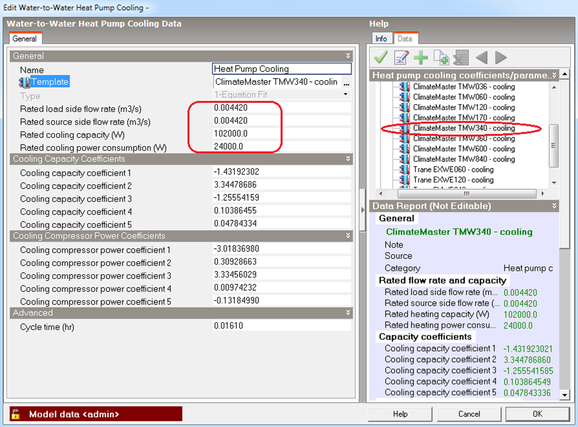
Navigate to the Heat pump cooling component and edit it. Load an appropriate heat pump model from template using the heat pump Rated cooling capacity data to match the heat pump with the design cooling load calculated in step 2. You can see in the example below a heat pump having 102 kW has been selected to meet the peak cooling load of 85 kW giving some spare capacity.
Alternatively you can create your own cooling capacity coefficients and cooling compressor power coefficients together with rated flow rates, rated heating capacity and rated cooling power consumption from catalogue data.
Note that the rated load side flow rate for the selected heat pump is 0.00442 m3/s.
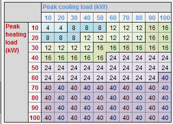
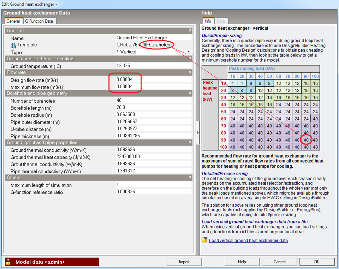
Open the Ground heat exchanger dialog and use the quick sizing table (below) to decide which template to load. Rounding up design heating and cooling loads from 85 kW to 90 kW you can see that 40 boreholes are required to meet this combination of loads.
Change both Design flow rate and Maximum flow rate to 0.00884 which is the sum of 0.00442 + 0.00442 for the heat pump heating and heat pump cooling components respectively. Refer to steps 4 and 5. If you have used your own specific heat pump heating/cooling data generated from catalogue data you should alter this flow rate figure accordingly.
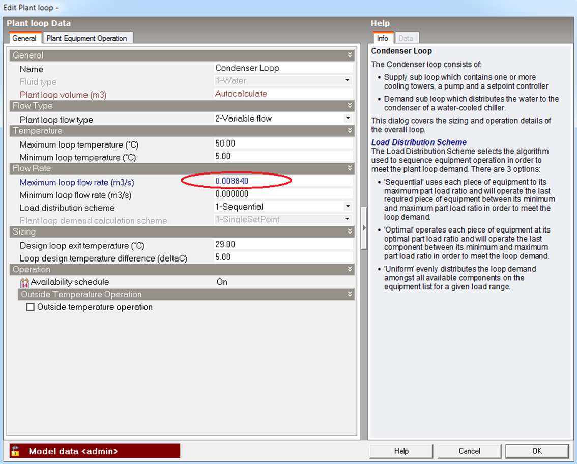
Change Maximum loop flow rate from Autosize to 0.00884, the same as (or greater than) ground heat exchanger flow rate, derived in step 6.
Important note: You must not use Autosize for condensers connected to GSHPs.
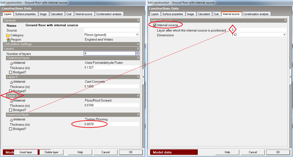
Edit any Ground floor, Internal floor or External floor constructions where the underfloor heating applies to ensure that an internal source is included in the construction.
To ensure the best heat transfer from the embedded hot water pipes to the room occupied region, the innermost layer (top layer) of the construction should have a relatively small thickness using thermally conductive timber flooring or tiles rather than a more insulating material such as carpet.
On the Internal source tab, check the Internal source option and assign the position of the internal source within the construction layers. The internal source layer should normally be placed at one layer below (inside) innermost layer.
(1) Summer modelling results:
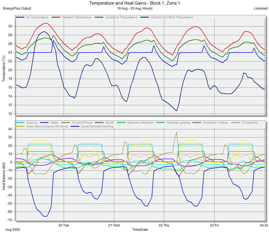
During occupied hours each day in summer, room air temperature was controlled well at 24ºC (cooling setpoint temperature is 24ºC).
(2) Winter modelling results:
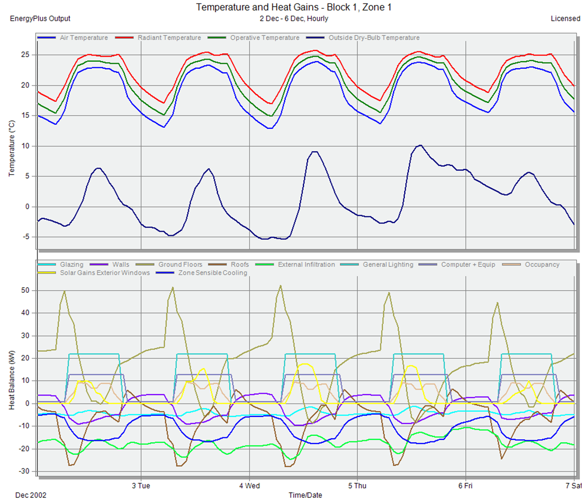
During occupied hours each day in winter, room air temperature was controlled at about 23ºC (heating setpoint temperature is 22ºC).