The air to water heat pump, aka air source heat pump (ASHP), is a compound object consisting of a water heater tank, a direct expansion (DX) “coil” (i.e., an air-to-water DX compression system which includes a water heating coil, air coil, compressor, and water pump), and a fan to provide air flow across the air coil associated with the DX compression system. These objects work together to model a system which heats water using zone air, outdoor air, or a combination of zone and outdoor air as the primary heat source.
Note: The terms "Air to water heat pump", "Air source heat pump" and "ASHP" are used interchangeably in the documentation.
Various configurations of tank location, inlet air source, and DX coil compressor location can be modelled.
Air to water heat pumps can be added in 3 main locations:
The heat pump water heater’s DX coil is the primary heat source and the water tank’s heater (element or burner) can provide supplemental heat as necessary. The model also assumes that the heat pump’s fan and water pump cycle on and off with the compressor.
The components making up the air to water heat pump are:
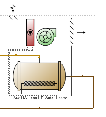
The ASHP HVAC template uses a more sophisticated way to combine ASHP and supplementary heating. The ASHP provides the main heating and a hot water loop with boiler is used to provide any additional heat required to meet the overall supply setpoint via a heat exchanger .

Example HVAC layout showing how ASHP output can be supplemented by heat from a hot water loop - ASHP
Enter a unique name for the air to water heat pump.
The availability schedule defines the times when the heat pump compressor is available to operate. A schedule value equal to 0 denotes that the heat pump compressor is off for that time period. A value other than 0 denotes that the heat pump compressor is available to operate during that time period. During times when the heat pump compressor is scheduled off, the heater (element or burner) in the water tank object operates based on its tank set point temperature schedule and the heat pump’s parasitic electric power is also off for that time period.
This schedule defines the set point (or “cut-out”) temperature for the heat pump compressor. Temperature values used in this schedule should be in degrees Celsius. The heat pump compressor cycles off when the tank water reaches this set point temperature. Once the heat pump compressor cycles off, the tank water temperature drops until it falls below the set point temperature minus the dead band temperature difference defined below (i.e., the “cut-in” temperature). At this point, the heat pump compressor cycles on and remains on until the heat pump compressor set point temperature is reached.
Important Note: The overall heat pump compressor “cut-in” temperature (Compressor setpoint temperature schedule value minus the dead band temperature difference below) must be greater than the Water Heater Setpoint temperature schedule ("cut-out" temperature) in order for the heat pump to provide heat to the water heater tank.
This numeric field contains the dead band temperature difference (in °C or °F). The heat pump compressor “cut-in” temperature is defined as the Compressor set point temperature defined above minus this dead band temperature difference. The heat pump compressor cycles on when the water temperature in the tank falls below the “cut-in” temperature. The heat pump compressor remains on until the water temperature in the tank rises above the compressor set point (“cut-out”) temperature defined above. The dead band temperature difference must be greater than 0°C and less than or equal to 20°C.
In this model, the heat pump water heater’s DX compression system is considered the primary heat source and the water tank’s heater (element or burner) provides supplemental heat as necessary. Therefore, the cut-in temperature for the heat pump compressor (set point minus dead band temperature difference) is usually higher than the set point temperature for the heater (element or burner) in the associated water heater tank object. At times when the water heater tank set point temperature is greater than the cut-in temperature of the heat pump compressor, the heat pump compressor is disabled and the tank’s heater is used to heat the water.
This numeric field contains the minimum inlet air dry-bulb temperature entering the air coil (evaporator) and fan section (in °C or °F) below which the heat pump compressor does not operate. The minimum inlet air dry-bulb temperature should be greater than or equal to -20°C.
Note: The minimum Minimum inlet air temperature for compressor operation setting allowed in DesignBuilder is -20°C, but if you intend to export the model to run outside DesignBuilder in EnergyPlus v8.6, the minimum temperature allowed is higher at -5°C. In this case, if you need to use a value lower than -5°C, you should either copy the idd file stored in the DesignBuilder EnergyPlus folder to the EnergyPlus folder you are using, or manually edit the EnergyPlus idd file. In EnergyPlus v8.9 and later, the minimum limit has been removed so this issue will not arise.
Select the location of the heat pump compressor and the air temperature for this location used to control operation of the compressor’s crankcase heater in the Air to water heat pump coil. Valid entries are:
The 2-Zone option is only available when the ASHP is used as an object placed within an HVAC zone.
This schedule is available when the 1-Schedule option is selected as the Compressor location above. It defines the ambient air temperature surrounding the heat pump compressor, which is used to control the compressor’s crankcase heater operation.
This numeric field contains the heat pump’s condenser water flow rate (in m3/s or gal/min). It is the actual condenser water flow rate to be simulated, which may differ from the Rated condenser water flow rate specified for the heat pump’s DX coil. This water flow rate must be greater than 0 or this field is autocalculatable. If autocalculated (field value = autocalculate), the condenser water flow rate is set equal to the rated heating capacity of the heat pump’s DX coil multiplied by 4.487E-8 m3/s/W. When this flow rate is different from the Rated condenser water flow rate specified for the heat pump’s DX coil, the user should also specify a Heating capacity function of water flow fraction curve and a Heating COP function of water flow fraction curve in the associated DX coil object to account for differences in capacity and power consumption at the off-rated water flow rate.
This numeric field contains the air flow rate across the heat pump’s air coil (evaporator) (in m3/s or ft3/min). It is the actual air flow rate to be simulated, which may differ from the Rated evaporator air flow rate specified for the heat pump’s DX coil. Values must be greater than 0 or this field is autocalculatable. If autocalculated (field value = autocalculate), the evaporator air flow rate is set equal to the rated heating capacity of the heat pump’s DX coil multiplied by 5.035E-5 m3/s/W. When this flow rate is different from the Rated evaporator air flow rate specified for the heat pump’s DX coil, the user should also specify a Heating capacity function of air flow fraction curve and a Heating COP function of air flow fraction curve in the associated DX coil object to account for differences in capacity and power consumption at the off-rated water flow rate.
Select the configuration of the air flow path through the heat pump air coil (evaporator) and fan section. Valid entries are:
Select the schedule used to define the dry-bulb temperature of the inlet air to the heat pump air coil (evaporator) and fan section. Schedule values should be in degrees Celsius. This field is only required when the Inlet air configuration defined above is specified as 1-Schedule.
Select the schedule used to define the humidity of the inlet air to the heat pump evaporator and fan section. Schedule values must be entered as relative humidity fraction from 0 to 1 (e.g., a schedule value of 0.5 means 50%RH). This field is only required when the Inlet air configuration defined above is specified as 1-Schedule.
If the Inlet air configuration is specified as 4-Zone and outdoor air you must select the Inlet air mixer schedule which defines whether the heat pump draws its inlet air from the zone, outdoors, or a combination of zone and outdoor air. A schedule value equal to 0 indicates that the heat pump draws its inlet air from the zone. A schedule value equal to 1 denotes that the heat pump draws its inlet air from outdoors. Values between 0 and 1 denote a mixture of zone and outdoor air proportional to the schedule value. The Inlet air mixer schedule controls both the inlet air mixer and outlet air splitter nodes in unison to ensure that the operation of the heat pump does not contribute to zone pressurization or depressurization. For example if the Inlet air mixer schedule value is 0.4, then the inlet air mixer node is composed of 40% outdoor air and 60% zone air. For this same case, the outlet air splitter directs 60% of the ASHP outlet air back to the zone and 40% of the outlet air flow is exhausted outdoors.
This Selection defines the placement of the fan in the heat pump water heater. Valid choices are:
This numeric field contains the on-cycle parasitic electric power (in W). This is the parasitic electric power consumed by controls or other electrical devices associated with the heat pump water heater. This parasitic electric load is consumed whenever the heat pump compressor is operating and the model assumes that this parasitic power does not contribute to heating the water. This parasitic load does, however, affect the zone air heat balance when the heat pump water heater sends some or all of its outlet air to a zone (i.e., Inlet air configuration field specified as 2-Zone air only, or 4-Zone and outdoor air) and the Parasitic heat rejection location field is specified as 1-Zone. The minimum value for this field is 0.0, and the default value is also 0.0.
This numeric field contains the off-cycle parasitic electric power (in W). This is the parasitic electric power consumed by controls or other electrical devices associated with the heat pump compressor. This parasitic electric load is consumed whenever the heat pump water heater is available but the compressor is not operating, and the model assumes that this parasitic power does not contribute to heating the water. This parasitic load does, however, affect the zone air heat balance when the heat pump water heater sends some or all of its outlet air to a zone (i.e., Inlet air configuration field specified as 2-Zone air only, or 4-Zone and outdoor air) and the Parasitic heat rejection location field is specified as 1-Zone. The minimum value for this field is 0.0, and the default value is also 0.0.
Select where the on-cycle and off-cycle parasitic heat is rejected. Valid choices are: