Cooled beams are long rectangular finned tubes mounted at high level at regular intervals within a space. They provide quiet draught-free cooling with capacities up to about 150 W/m2. As the cooled beams cool the surrounding air, it falls into the occupied area below due its greater density. The beams are typically arranged at regular intervals above, or partly below, a false ceiling. A relatively small ceiling void depth is required.
It is important to ensure good air flow and so any ceiling tiles positioned below beams must have openings within the tiles equivalent to at least 50% of their area. In some cases beams are suspended below the ceiling.
Cooled beam systems require a separate constant volume ventilation system to supply fresh air to the space.
The EnergyPlus Cooled Beam system is a mixed air-hydronic system.. A central constant volume air system supplies conditioned ventilation air to the zones. Chilled water circulates through ceiling mounted cooled beam units at a rate suitable for meeting the zone sensible cooling load. Any dehumidification is done by the central ventilation air system. Heating is usually accomplished with hot water radiators/baseboards. Thermodynamically, the cooled beam system resembles the four-pipe induction unit.
To model a typical cooled beam system a conventional central constant volume forced air system can be used. This system will normally be 100% outside air delivered at a fixed supply temperature (which could be reset by schedule or by outside air temperature). On the supply side of this air loop there will be the usual central AC equipment: outside air mixer, fan, heating and cooling coil.
The cooled beam equipment in a zone is treated by the program as a single terminal unit, however the actual installation will have multiple beams in each zone. EnergyPlus calculates how many beams of what length are needed to meet the zone design load during its sizing calculation for the system.
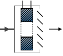
The images below (reproduced with permission from CIBSE) illustrate the difference between the chilled ceilings described here and cooled beams.

CIBSE KS03 Figure 12

CIBSE Guide H Fig 5.79
Important Note: If an air loop is exclusively supplying cooled beams, the Air loop Type of load to size on setting should be set to 2-Ventilation requirement, otherwise the system air flow rate will be sized on the zone sensible load and the resulting flow rate may be too high for the cooled beams to maintain the zone setpoint temperatures.
Tip: A useful resource on chilled ceilings and cooled beams can be found at https://www.feta.co.uk/uploaded_images/files/CBCA/Chilled%20Beams%20Brochure_Final%207%20%28web%29.pdf
This is a read-only label that is automatically generated by the software and which incorporates the name of the zone in which the ADU is located.
Two types of units are modelled:
This is the air flow rate of the supply air entering the zone (in m3/s or ft3/min). This input would normally be autosized based on the zone ventilation requirement.
The maximum chilled water flow rate (in m3/s or gal/min) for the unit. This input would normally be autosized based on the zone design load.
The number of individual cooled beam units in the zone. Normally this unit would be auto-sized by the program based upon the previous field and the nominal flow rate for a single beam unit (set by the program to 0.07 kg/s).
This is the length of an individual beam in metres. Normally this will be auto-sized by the program based upon the number of beam units and the zone design sensible cooling load. 1 to 4 meters is a typical length range.
The nominal or design inlet water temperature (in °C or °F). The default is 15°C.
The nominal or design outlet water temperature (in °C or °F). The default is 17°C.
The following inputs are parameters used to characterize the performance of the chilled beam units. Values for a given unit can be obtained from the manufacturer. The parameters are used in the following equations.
| Pbeam = A×K×ΔT | beam cooling output per unit length W/m |
| K=α×ΔTn1×v×ρn2×ωn3 | coil heat transfer coefficient W/(m2K) |
| Vρ =(qin/α0)×ρair | room air mass flow rate across coil kg/(m2s) |
| qin = K1×ΔTn + Kin×qpr | volumetric flow rate across coil per unit length m3/(s-m) |
Where:
ΔT is the room air – water temperature difference (average water temperature is used) in °C.
ω is the water velocity in m/s.
qpr is the supply air flow rate per unit length m3/ (s-m)
This is the surface area on the air side of the beam per unit beam length (in m2/m or ft2/ft). The default is 5.422. This is A in the equations above.
This is the coefficient of induction Kin in the equations above. The default is 2.0 for active beams and 0.0 for passive beams.
This is the water pipe inside diameter (in m or in). The default is 0.0145.
This is α in the above equations. The default is 15.3
This is n1 in the above equations. The default is 0.
This is n2 in the above equations. The default is 0.84.
This is n3 in the above equations. The default is 0.12.
This is α0 in the above equations. It is the free area of the coil in plan view (for the air flow) per unit beam length. The units are square meters per meter. The default is 0.171.
This is K1 in the above equations. The default is 0.005.
This is n in the above equations. The default is 0.4.
This is the schedule that determines whether or not the unit is available for each timestep of the simulation. A schedule value greater than 0 (usually 1 is used) indicates that the unit can be on during the timestep . A value less than or equal to 0 (usually 0 is used) denotes that the unit must be off for the timestep .