Demand control ventilation (DCV) is a ventilation system capability that provides automatic reduction of outdoor air intake below design rates when the actual occupancy of spaces served by the system is less than design occupancy. In most commercial buildings ventilation is provided to deal with two types of indoor pollution: odours from people, and off-gassing from building components and furniture. When a space is vacant, it has no people pollution so the people-related ventilation rate is not needed. Many types of high-occupancy spaces, such as classrooms, multi-purpose rooms, theatres, conference rooms, or lobbies have ventilation designed for a high peak occupancy that rarely occurs.
Demand-controlled ventilation has the potential to provide significant HVAC energy savings by conditioning only the amount of ventilation air necessary to maintain good indoor air quality. It can be particularly effective in buildings or zones that have widely varying occupancy.
DCV is most successful when reducing ventilation rates – and so reducing fan energy use – when meeting the demands of indoor air quality (IAQ). It is not necessarily so successful, in energy terms, for high design cooling loads, since airflows will increase above the required IAQ minimum to meet space cooling loads. Practically, this is likely to mean that IAQ-driven DCV is most effective in ASHRAE climate zones 4 and above.
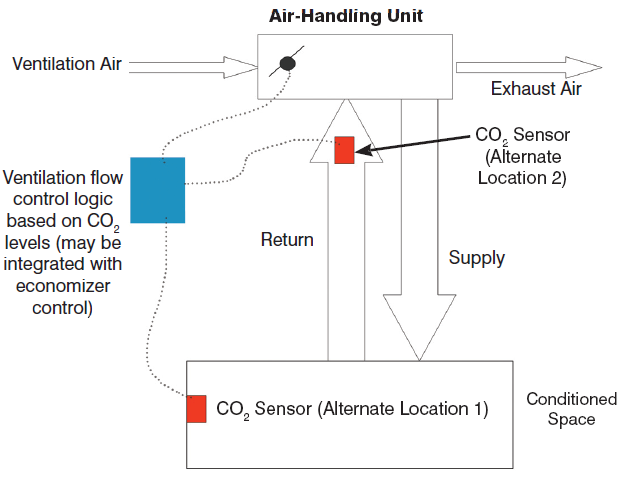
Schematic of a typical DCV system from Demand-Controlled Ventilation and Sustainability with permission from author Tom Lawrence and ASHRAE.
This section provides a summary of the steps required to model an air system with DCV outdoor air control in DesignBuilder.