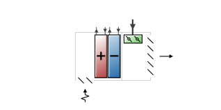
The four pipe induction terminal unit provides local hot water heating or chilled water cooling of induced zone air which then mixes with centrally conditioned supply air. An air conditioning system consisting of these terminal units is effectively a mixed central air/local hydronic system. The centrally conditioned air supplied to the induction terminal units is constant volume at quite high pressure. The central air is discharged through a nozzle in the terminal unit, inducing a flow of room air over a hydronic heating/cooling coil. The coil is connected either to a single inlet and outlet pipe (2 pipe unit) or to 2 inlets and 2 outlets (4 pipe unit). The heated or cooled induced air mixes with the centrally conditioned air before being discharged into the zone. The terminal units are usually expected to do only sensible cooling – any dehumidification is done by the central air conditioning system.
The EnergyPlus model of the four pipe induction terminal unit is a compound component consisting of a hot water heating coil, a chilled water cooling coil, and an air mixer. The unit has two inlet air streams: the centrally conditioned supply air and the induced air from the zone. The induced air passes first through the heating coil, then through the cooling coil and finally through the mixer. The central supply air goes directly into the mixer. The water flow through the hot or cold water coil is varied to meet the zone air conditioning requirement. Note that EnergyPlus models the four pipe induction terminal unit as having separate heating and cooling coils whereas real units have only a single coil used for both heating and cooling. Note also that the four pipe induction unit model can be used to model a two pipe unit by simply adjusting the heating and cooling coil schedules so that the heating coil is off when the cooling coil is on and vice versa.
This is a read-only label that is automatically generated by the software and which incorporates the name of the zone in which the ADU is located.
The maximum volumetric air flow rate discharged from the unit (in m3/s or ft3/min). Since this is a constant air volume unit, this is also the design, rated air flow rate of the unit. Note that this is the total discharge flow rate – including both central supply and induced air.
The ratio of induced air flow rate to primary supply air flow rate. The default is 1.0 –the supply air induces an equal amount of zone air.
This section is visible only if the heating coil sub-component of this ADU has Type 1-Water.
The maximum hot water volumetric flow rate (in m3/s or ft3/min) through the unit’s heating coil if a water coil has been selected. This value may be auto-sized.
The minimum hot water volumetric flow rate (in m3/s or ft3/min) through the unit’s heating coil if a water coil has been selected. This value may be auto-sized.
The maximum cold water volumetric flow rate (in m3/s or ft3/min) through the unit’s cooling coil. This value may be auto-sized.
The minimum cold water volumetric flow rate (in m3/s or ft3/min) through the unit’s cooling coil. This value may be auto-sized.
This is the schedule that determines whether or not the unit is available for each timestep of the simulation. A schedule value greater than 0 (usually 1 is used) indicates that the unit can be on during the timestep . A value less than or equal to 0 (usually 0 is used) denotes that the unit must be off for the timestep .
This is the control tolerance for the unit heating output. The unit is controlled by matching the unit output to the zone demand. For units with water coils, the model must be numerically inverted to obtain a specified output. The convergence tolerance is the error tolerance used to terminate the numerical inversion procedure. Basically this is the fraction:
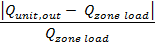
This is the control tolerance for the unit cooling output. The unit is controlled by matching the unit output to the zone demand. The model must be numerically inverted to obtain a specified output. The convergence tolerance is the error tolerance used to terminate the numerical inversion procedure. Basically this is the fraction: