Powered Induction units (also known as fan-assisted terminal units) ensure that dumping of the supply air will not occur. They contain a small fan which mixes the supply air with re-circulated room air to provide a constant volume supply to the space. The mixing of the two streams is controlled to achieve an air temperature that satisfies the cooling load for the zone being served. Induction units generally have higher capital and maintenance costs and also the potential for increased noise levels.
The EnergyPlus parallel powered induction unit (PIU) is an air system terminal unit that mixes varying amounts of secondary (re-circulated) air and primary (conditioned supply) air to produce a variable total flow of air to a zone. The unit contains a small fan that acts to induce the secondary air and a heating coil for heating the mixed secondary and primary air. The secondary and primary air streams enter the unit in parallel. The fan sits in the secondary air stream and runs only when secondary air is needed. The primary air inlet contains a damper that can move from fully open (maximum primary air) to a minimum stop (minimum primary air).
At full cooling load the primary air damper is fully open and the fan is off. The primary air flow is at maximum and there is little or no secondary air flow. As the cooling load decreases, the primary air damper gradually closes and the secondary air flow remains close to zero. At some point, usually when the primary air flow has reached the minimum, the fan switches on and secondary air is induced. The heating coil will switch on as needed to meet any heating demand.
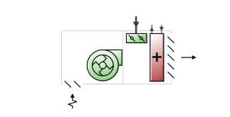
The EnergyPlus model of the parallel PIU terminal unit is composed of three components: a constant volume fan, a zone mixer, and a heating coil (water, electric or gas):
This is a read-only label that is automatically generated by the software and which incorporates the name of the zone in which the ADU is located.
This is the fraction of the primary air flow at which fan turns on. In the parallel PIU the fan operation is intermittent. If the primary air flow is above this fraction of the maximum, the fan is off. Otherwise it is on.
This is the maximum volumetric air flow rate of primary air through the unit (in m3/s or ft3/min). This is the primary air flow rate at full cooling load when the primary air damper is fully open.
This is the maximum volumetric air flow rate of secondary air through the unit (in m3/s or ft3/min). This flow rate can be any amount but is commonly less than the maximum primary air flow rate.
This is the minimum volumetric air flow rate of primary air through the unit expressed as a fraction of the maximum volumetric air flow rate of primary air. This input can be 0.0.
This section is visible only if the heating coil sub-component of this ADU has Type 1-Water.
The maximum hot water volumetric flow rate (in m3/sec or gal/min) through the unit’s heating coil if a water coil has been selected. This value may be auto-sized.
The minimum hot water volumetric flow rate (in m3/sec or gal/min) through the unit’s heating coil if a water coil has been selected. This value may be auto-sized.
This is the schedule that determines whether or not the unit is available for each timestep of the simulation. A schedule value greater than 0 (usually 1 is used) indicates that the unit can be on during the timestep . A value less than or equal to 0 (usually 0 is used) denotes that the unit must be off for the timestep .
This is the control tolerance for the unit heating output. The unit is controlled by matching the unit output to the zone demand. For units with water coils, the model must be numerically inverted to obtain a specified output. The convergence tolerance is the error tolerance used to terminate the numerical inversion procedure. Basically this is the fraction: