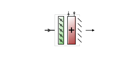
Variable air volume (VAV) systems control the dry-bulb temperature inside a zone by varying the supply air volume instead of the air temperature. At full cooling the VAV damper is fully open supplying the specified maximum air flow rate. As the cooling load decreases, the damper closes until it reaches the minimum stop specified by the zone minimum air flow fraction.
VAV systems can be used for interior or perimeter zones with a common fan system, air temperature control, and reheating devices. The VAV concept may vary according to the VAV box locations, air temperature controls and types of heating elements. Heating can usually be provided by use of reheat coils or thermostatic baseboard.
The unit contains a single heating coil which can be edited to change the type to 1-Water, 2-Electric or 3-Gas.
This is a read-only label that is automatically generated by the software and which incorporates the name of the zone in which the ADU is located.
The damper heating action determines the damper action in the terminal unit as the zone moves above or below the zone setpoint. With both control options, the damper is at the minimum air flow rate whenever the zone temperature is between the cooling and heating setpoints (deadband condition).
With 1‑Normal (the default) action, the damper will remain at the minimum air flow rate during heating operation. As the heating load increases, the water flow rate in the reheat coil will be increased to maintain temperature in the zone until the maximum water flow rate is reached or the user-specified maximum reheat air temperature is reached.. This is sometimes called the single maximum control logic as illustrated below.
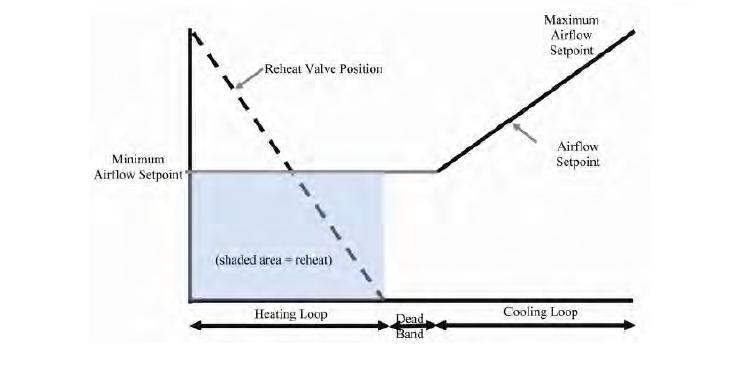
Single Maximum Control Logic
With 2‑Reverse, as the heating load increases, the unit starts at minimum air flow and minimum hot water flow. The hot water flow is increased until it reaches maximum flow or the user-specified maximum reheat air temperature is reached, then the air damper starts to open to meet the load. This option is used if the minimum air flow rate is not adequate to serve the peak heating load. This is sometimes called the dual maximum control logic as illustrated in the following figure. For an electric heating coil, the reverse action works the same as the normal action – always keeping the air flow at the minimum during heating.
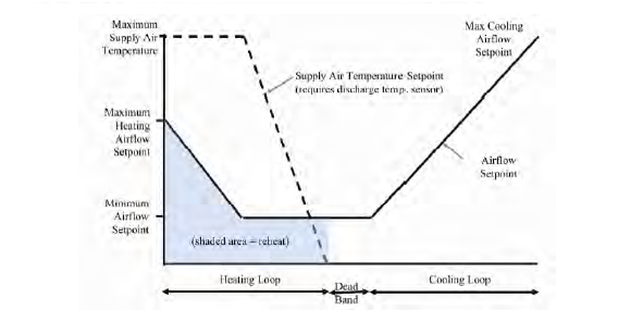
Dual Maximum Control Logic
This is the maximum supply air temperature (°C) leaving the reheat coil in the VAV terminal unit during heating operation.
The design maximum volume flow rate (m3/sec) specified for the ADU. This field may be auto-sized.
This is used to select how the software will determine the minimum flow rate to the zone while the system is operating. There are three choices for selecting how the minimum flow rate is specified:
This item will only appear if 3‑Scheduled is selected as the Zone minimum air flow method. It can be used to control the air flow rate used to size the unit heating coil if the coil is a water coil and the water flow rate for the coil is set to be auto-sized. The Air flow control for coil sizing drop-list contains three options:
If 1-None is selected, then the air flow rates used for sizing normal-action reheat coils is the average of the minimum and maximum values in this schedule. The air flow rate used for reheat coil sizing is reported with other component sizing information as Reheat coil sizing air volume flow rate.
If 1‑Constant is selected for the Zone minimum air flow method, then the turndown ratio is used to define the minimum flow rate to the zone specified as a fraction of the maximum air flow rate while the system is operating. The minimum zone fraction is normally specified to meet the minimum ventilation requirement for the occupants. The reheat coil operates only when the damper is at this minimum flow rate when Damper heating action is set to 1-Normal (the default).
If 2‑Fixed flow rate is selected for the Zone minimum air flow method, then this setting is used to define the minimum flow rate (m3/s) to the zone specified as a fixed air flow rate while the system is operating. The minimum air flow rate is normally specified to meet the minimum ventilation requirement for the occupants. The reheat coil operates only when the damper is at this minimum flow rate when Damper heating action is set to 1-Normal (the default). This field is used if the Zone minimum air flow method field is set to 2‑Fixed flow rate.
If 3‑Scheduled is selected for the Zone minimum air flow method, then this setting is used to define the schedule that determines the value of the minimum air flow fraction. The schedule should contain fractions from 0.0 to 1.0. These values will define the minimum flow rate to the zone while the system is operating, specified as a fraction of the maximum air flow rate. The reheat coil operates only when the damper is at this minimum flow rate when Damper heating action is set to 1-Normal (the default).
This section is visible only if the heating coil sub-component of this ADU has Type 1-Water.
The maximum hot water volumetric flow rate (in m3/s or gal/min) through the unit’s heating coil if a water coil has been selected. This value may be auto-sized.
The minimum hot water volumetric flow rate (in m3/s or gal/min) through the unit’s heating coil if a water coil has been selected. This value may be auto-sized.
This item is only available if the reheat coil is a water coil and the Damper heating action is set to 2-Reverse. There are two available options:
These methods are used to calculate the maximum allowable air flow rate during reheat operation. If 1‑None is selected, the maximum flow will not be limited. If Control on outdoor air flow is selected, the limit established through a 2-Maximum flow control during reheat option may be increased by the software to meet the outdoor air flow rate requirement. At no time will the maximum flow rate calculated here exceed the value for Maximum air flow rate.
This limit is active only when the zone thermostat requests heating and the VAV box damper is reverse acting.
This factor (m3/s-m2) is multiplied by the zone area, to determine the maximum volume flow rate (m3/s) allowed during reheat operation (see detailed explanation above). This field may be auto-calculated by entering “autocalculate”. If auto-calculated, the value is set to 0.002032 m3/s-m2 (0.4 cfm/ft2).
This fraction is multiplied by the Maximum air flow rate to determine the maximum volume flow rate (m3/s) allowed during reheat operation (see detailed explanation above). This field may be auto-calculated by entering “autocalculate”. If auto-calculated, the value is set to 0.002032 m3/s-m2 (0.4 cfm/ft2) multiplied by the zone floor area divided by the Maximum air flow rate.
If this option is selected, the terminal unit will increase flow as needed to meet the outdoor air requirement specified on the HVAC zone dialog. If Outdoor air flow per person is non-zero, then the outdoor air requirement will be calculated by the software based on the current number of occupants in the zone. At no time will the supply air flow rate exceed the value for Maximum air flow rate. If this option is not selected, then the terminal unit will not be controlled for outdoor air flow.
This is the schedule that determines whether or not the unit is available for each hour of the simulation. A schedule value greater than 0 (usually 1 is used) indicates that the unit can be on during the hour. A value less than or equal to 0 (usually 0 is used) denotes that the unit must be off for the hour
The coil is controlled by knowing the zone demand determined by the zone thermostat and setting the outlet conditions to meet this demand. For the electric and gas coils, this is set exactly since the coil model solution can be inverted. With the hot water coil that uses an effectiveness-NTU method, the solution cannot be inverted directly. Therefore, to determine the correct mass flow rate for the hot water the solution is solved for by iteration. The iterative solution uses an interval halving routine and needs a termination criterion that is set with the Convergence tolerance parameter. This control offset is set to a decimal fraction of the zone demand as the criteria, i.e. 0.001. The default for the field is 0.001.