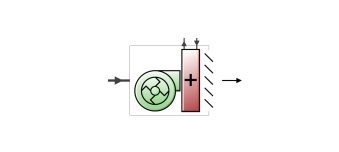
The VAV terminal unit with variable-speed fan and reheat coil is an air system terminal unit consisting of a variable speed fan in series with a heating coil. These units are usually employed in under-floor air distribution (UFAD) systems where the air is supplied at low static pressure through an under-floor plenum. The fan is used to control the flow of conditioned air that enters the space. When the fan is off the plenum pressure drives the minimum air flow through the terminal unit. At maximum cooling the fan runs at its maximum speed. At full heating the fan runs at its heating maximum – usually less than the cooling maximum flow rate. Thus this unit has two separate maximum flow rates – one for heating and one for cooling.
For cooling, control is maintained simply by varying the fan speed. For heating, the unit first tries to meet the heating load by varying the heating coil output while keeping the air flow at minimum (fan off). If this is not adequate the fan turns on and operates in variable flow mode up to the heating maximum flow rate. This unit is modelled in EnergyPlus as a compound component – a variable speed fan and a heating coil in series in the air stream. The unit is blow through – the fan is upstream of the heating coil.
The heating coil can be edited to change the type to 1-Water, 2-Electric or 3-Gas.
Note: When using the VAV with VS fan and reheat coil ADU, the associated AHU must have the extract fan option switched OFF.
This is a read-only label that is automatically generated by the software and which incorporates the name of the zone in which the ADU is located.
This is the maximum volumetric air flow rate (in m3/s or ft3/min) through the unit when the thermostat is calling for cooling. Normally this is the same as the unit’s fan maximum volumetric flow rate.
This is the maximum volumetric air flow rate (in m3/s or ft3/min) through the unit when the thermostat is calling for heating.
This is the minimum flow rate to the zone while the system is operating, specified as a fraction of the maximum air flow rate. For this unit this is the flow rate when the fan is off.
This section is visible only if the heating coil sub-component of this ADU has Type 1-Water.
The maximum hot water volumetric flow rate (in m3/s or gal/min) through the unit’s heating coil if a water coil has been selected. This value may be auto-sized.
The minimum hot water volumetric flow rate (in m3/s or gal/min) through the unit’s heating coil if a water coil has been selected. This value may be auto-sized.
This is the schedule that determines whether or not the unit is available for each timestep of the simulation. A schedule value greater than 0 (usually 1 is used) indicates that the unit can be on during the timestep . A value less than or equal to 0 (usually 0 is used) denotes that the unit must be off for the timestep .
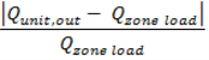
This is the control tolerance for the unit heating output. The unit is controlled by matching the unit output to the zone demand. The model must be numerically inverted to obtain a specified output. The convergence tolerance is the error tolerance used to terminate the numerical inversion procedure. Basically this is the fraction: