
As soon as a new analysis data set has been created, a default CFD grid is generated using the default grid spacing defined as part of the data set. The default grid may be edited using the ‘Edit CFD Grid’ tool which allows you to change the spacing used for default regions, insert additional regions or remove previously inserted regions.
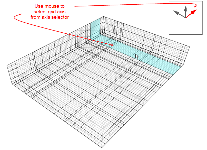
When you select the ‘Edit CFD Grid’ tool, the grid is displayed with the building outline overlaid as a ghosted wire frame. Grid regions are displayed along the major axes bounded by dark grey lines, the auto-generated grid region spacing lines being displayed in a lighter grey. The currently selected grid region is selected in cyan or yellow if the region is a non-default inserted region. To select regions on one of the other major axes, you can change the axis by clicking on the required axis of the axis selector displayed at the top right of the screen:
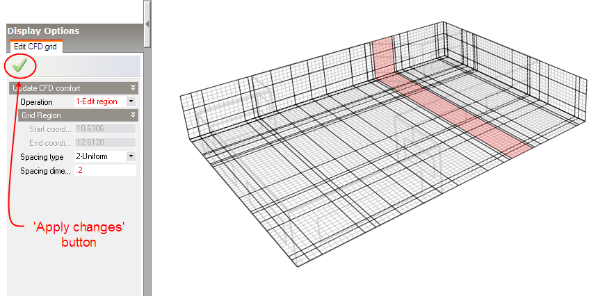
To edit a grid region, move the mouse cursor across the grid to the required region that will highlight to indicate that it has been selected and then click the mouse button. The selected region will then highlight in red and the ‘Edit CFD Grid’ data panel will be displayed at the bottom left of the screen:
The following settings are available on the Edit CFD Grid data panel:
If the ‘Insert Region’ operation has been selected, this setting is displayed allowing you to define a custom coordinate within the current region. Note that the coordinate must lie in the range defined by the displayed start and end coordinates.
The spacing type can be set to one of the following:
For i <= n/2: xi=[(region dimension)/2](2i/n)power+xs
For i >= n/2: xi=[(region dimension)/2][2-(2i/n))power]+xs
If the uniform spacing type has been selected, this setting is displayed and allows you to enter the dimension used for sub-dividing the region.
If the Increasing/Decreasing/Symmetric power law spacing type has been selected, this setting is displayed and allows you to enter the power used in the associated power-law spacing relationship.
If the Increasing/Decreasing/Symmetric power law spacing type has been selected, this setting is displayed and allows you to enter the number of divisions used in the associated power-law spacing relationship.
After selecting an operation and adjusting the required settings, you then need to click on the ‘Apply changes’ button to update the selected grid region with the current settings.