HVAC tab in model data under Mechanical Ventilation header - Simple HVAC
When using Simple HVAC, enter the type of fan. Select from:
Note that in Simple HVAC the Auxiliary energy data accounts for all electric fan and pump distribution energy plus controls and any other electrical energy use associated with HVAC that is not already accounted for elsewhere.
Enter the pressure rise at full flow and standard conditions. Standard conditions are considered 20°C at sea level, 101325 Pa.
You can calculate the approximate fan pressure rise from Specific Fan Power (SFP) data using:
Delta P = 1000 * SFP * Fan total efficiency
Annex E of ISO 5801 shows that by rearranging the formula it can be derived that the SFP is a function of fan pressure divided by the efficiency of the fan system. Therefore the SFP will increase or decrease with a respective increase or decrease in the system pressure.
The SFP is a function of the volume flow of the fan and the electrical power input and is quoted for a particular flow rate;
SFP = Pe/ V
Where:
V is volume flow (l/s)
Peis electrical power input (W) to the fan system or complete air movement installation
[Reference FMA, UK, 2006]
Typical values for various system types are shown in the table below.
|
System Type |
Specific Fan Power (W/l-s) |
|
Central mechanical ventilation including heating, cooling and heat recovery |
2.5 |
|
Central mechanical ventilation including heating and cooling |
2.0 |
|
All other systems |
1.8 |
|
Local ventilation units within the local area, such as window/wall/roof units, serving one room/area |
0.5 |
|
Local ventilation units remote from the local area, such as ceiling void or roof mounted units, serving one room/area |
1.2 |
|
Fan coil units (rating weighted average) |
0.8 |
Enter the product of the fan motor and impeller efficiency of the supply fan. This is the ratio of the power delivered to the air to the electrical input power at maximum flow expressed as a percentage. The motor efficiency is the power delivered to the shaft divided by the electrical power input to the motor. The fan efficiency is power delivered to the air divided by the shaft power. The power delivered to the fluid is the mass flow rate of the air multiplied by the pressure rise divided by the air density. Must be greater than 0 and less than or equal to 100.
Enter the percentage of the motor heat that is added to the air stream. A value of 0 means that the motor is completely outside the air stream. A value of 100 means that all of the motor heat will go into the air stream and act to cause a temperature rise. Must be between 0 and 100.
Enter the supply fan placement type. There are two choices:
The default is 1-Draw through.
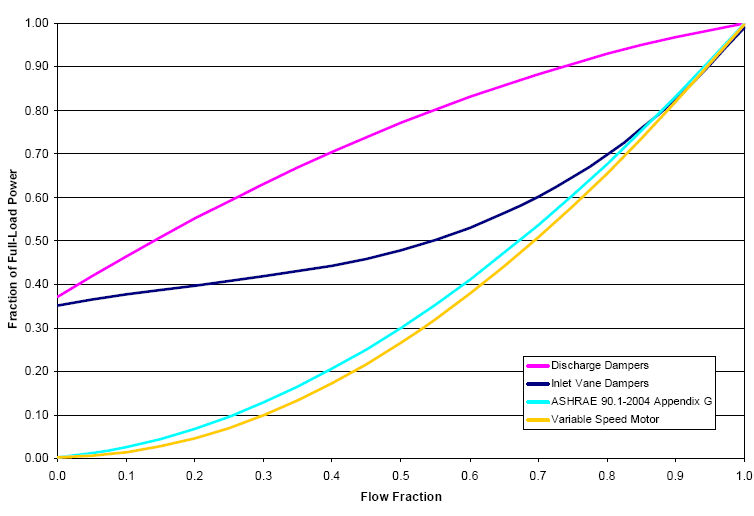
Select the set of generic pre-defined coefficients to use for the supply fan part-load power consumption. Choices are:
The resulting power curves are shown in the graph below. The ASHRAE 90.1-2004 Appendix G coefficients are from TABLE G3.1.3.15, Method 2. The other sets of coefficients are from the EnergyPlus Input Output Reference, Fan Coefficient Values table.
The calculations for fan power and airflow temperature pick up are detailed in the Energy![]() Related TopicsPl
Related TopicsPl![]() Related Topicsus Engin
Related Topicsus Engin![]() Related Topicseering reference. A summary is provided below:
Related Topicseering reference. A summary is provided below:
Total Fan Power = Mass flow rate. DeltaP / (Total fan efficiency . Air density)
Shaft Fan Power = Motor efficiency . Total Fan Power
Heat to air = Shaft Fan Power + (Total Fan Power - Shaft Fan Power) . Motor in air fraction