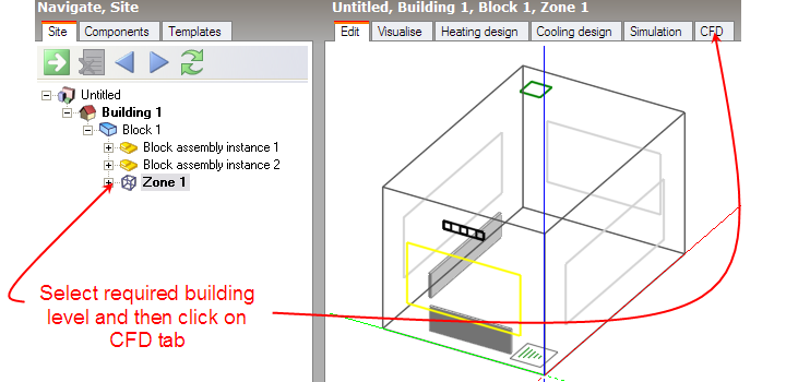
To create a new internal CFD analysis, first make sure that you have selected the appropriate level object (building, block or zone) in the model navigator and then click on the CFD screen tab:
The New CFD Analysis dialog is displayed which allows you to name the analysis and define grid generation variables:
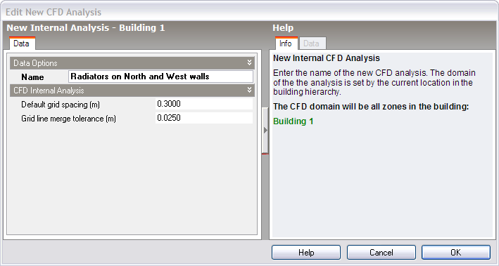
On entry to the CFD screen after completing and closing the new CFD analysis dialog, the CFD grid is automatically generated throughout the overall external domain extents. The grid is created by first determining key points obtained from constituent model blocks along the major axes, the distance between each of these key points being known as grid regions. Each CFD grid region along each major axis is automatically spaced using the ‘default grid spacing’ dimension.
A potential problem when generating the grid is the creation of cells with a high aspect ratio that can lead to instability in the equation solver. In order to avoid such cells, grid lines that are very close together can be merged. The grid line merge tolerance is the maximum dimension that will be used in determining whether or not to automatically merge grid lines.