
Vertical ground heat exchangers typically use boreholes containing U-tubes as shown in the figure below.
The EnergyPlus Ground Heat Exchanger (GHE) is a condenser component serving the condenser supply side alongside cooling towers and other condensing components.
The heat exchanger response is defined by a G-function. This is a non-dimensional function that is used to calculate the response to square heat pulses of different duration. (This function is not the same as ‘G-factors’ referred to in the ASHRAE Applications Handbook).
This continuous function is specified by a series of data pairs (LNTTSi, GFNCi) where:
The G-function is different for each borehole field configuration (i.e. a 4x4 field has a different response than a 80x80 field) and the borehole thermal resistance. It is also dependant on the ratio of borehole spacing to depth. G-function values, for accurate simulation, have to be calculated for each specific heat exchanger design. This can be done using some commercial ground loop heat exchanger design tool and the like. A reference data set, containing examples input data for 1x2, 4x4 and 8x8 configurations and for both standard and thermally enhanced grout, have also been provided. These data are provided as examples
only.
Further details on the implementation of this model can be found in:
Murugappan, A. Implementing Ground Source Heat Pump and Ground Loop Heat Exchanger Models in the EnergyPlus Simulation Environment. M.S. Thesis, Oklahoma State University, December 2002.
This alpha field contains an editable identifying name for the ground heat exchanger.
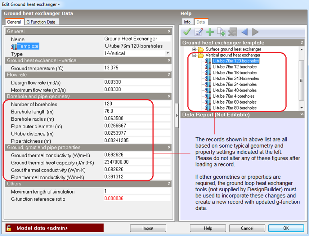
You can use this control to load data to the dialog from a pre-defined Ground heat exchanger template as a starting point for your particular component.
Note: After loading a Ground heat exchanger template it is important to make sure to update the Design heat exchanger flow rates as the sum of connected heat pump rated flow rates.
DesignBuilder provides 3 different ground heat exchanger types:
Note: The Type drop down list is not editable. To select a different type of heat exchanger, you must first select an appropriate template (above).
This numeric field contains the thermal conductivity of the ground (in W/m-K or Btu-in/h-ft2-F).
This numeric field contains the thermal heat capacity of the ground (in J/m3-K or Btu/ft3-F).
This numeric field contains the far field temperature of the ground (in °C or °F).
This numeric field contains the design volume flow rate of the GHE (in m3/s or gal/min). The flow rate specified is the total flow rate for the entire borehole field. Flow will be assumed to be evenly distributed across all boreholes.
This numeric field contains the number of bore holes in the GHE installation.
This numeric field indicates the depth of the top of the borehole below the ground surface (in m or ft). The depth measured from the ground surface downward is positive.
This numeric field contains the active length of the borehole (in m or ft), referenced from the starting location (potentially below the ground surface), to the end of the borehole.
This numeric field contains the diameter of the borehole (in m or in).
This numeric field contains the outer diameter of the U-tube (pipe) (in m or in).
This numeric field contains the thickness of the pipe (in m or in).
This numeric field contains the distance between the two legs of the U-tube (in m or ft). Distance is measured from the U-tube pipe centre.
This numeric field contains the thermal conductivity of the filler material (in W/m-K or Btu-in/h-ft2-F).
This numeric field contains the thermal heat capacity of the grout (in J/m3-K or Btu/ft3-F).
This numeric field contains the thermal conductivity of the pipe in (in W/mK or Btu-in/h-ft2-F).
This numeric field contains the thermal heat capacity of the pipe (in J/m3-K or Btu/ft3-F).
The G-Functions may be formulated slightly differently based on the program which generated them. The “raw” G-Functions are based on an borehole radius to active length ratio of 0.0005. If the physical ratio is different from this, a correction must be applied. EnergyPlus will apply the correction, based on the reference ratio entered in this field. There are therefore two possible input configurations:
The software GLHEPRO has been making this “pre-correction” to the data sets since version 3.1 of that software, so this input field should match the actual (physical) radius/length ratio.
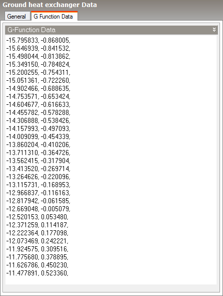
The borehole response is defined by a non-dimensional ‘G-function’ and the second tab includes a large text box with a list of G-function data pairs. The list is specified as a series of data points giving values of non-dimensional time vs G-function value (LNTTS1, GFUNC1), (LNTTS2, GFUNC2), (LNTTS3, GFUNC3) …….. (LNTTSn, GFUNCn)..
This numeric field contains the natural log of time/steady state time: ln(T/Ts).
This numeric field contains the G-function value of the corresponding LNTTS.
Example data:
 You can learn more about practical aspects of Ground Heat Exchanger design and simulation for project work by watching our webinar: Design and Modelling of Ground Source Heat Pump Systems
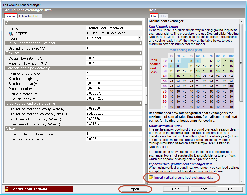
DesignBuilder provides a quick, approximate way to size vertical ground loop heat exchangers assuming typical borehole layouts and ground properties. The procedure is to use DesignBuilder Heating design and Cooling design calculations to obtain peak heating and cooling loads in kW, then use the table below to look up the minimum number of boreholes for the model.
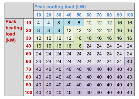
Then load the "U-Tube 76m xx-boreholes" vertical ground heat exchanger template with the corresponding number of boreholes from the template library. These templates include parameters pre-calculated based on a typical rectangular geometry and property settings (see left red-box in the figure below). Each includes a corresponding set of g-function data. For very different a bolehole layouts or when any of the ground or other parameter deviates significantly from these typical settings then you should use the Detailed design sizing method described below.
The net heating or cooling capacity of the ground over each season depends on the accumulated heat rejection/extraction, and therefore on the building loads throughout the whole year (not only the peak loads mentioned above), which might be available through simulation perhaps based on a simple HVAC setting in DesignBuilder.
Ground loop heat exchanger tools such as GLHEPRO and GLD (which are not supplied by DesignBuilder or EnergyPlus) are able to carry out a more detailed and accurate sizing calculation taking into account specific borehole layouts and ground properties. These tools can export calculated G-function data in the form of IDF files which can be loaded to the DesignBuilder Ground Heat Exchanger dialog as described below.
Data from a previously configured and sized vertical ground loop heat exchanger can be loaded by clicking on the Import button at the bottom of the dialog or the Import vertical ground heat exchanger data link from info panel (see figure below).
The corresponding g-function data will be loaded along with the rest of the data required on the dialog and can be viewed on the G Function Data tab.
DesignBuilder supports 4 different IDF GHE file formats which correspond to the versions of EnergyPlus targeted by the various versions of GLE and GLEHEPRO. The importer automatically identifies which of the formats below is being loaded and uses the appropriate IDD file for the import.
Tip: If the format of the GHE IDF file you are attempting to import is different from those illustrated below then you can manually adjust the format of the data in a text editor so it matches one of the supported formats.
Examples of the 4 supported GHE IDF formats are shown below.
This is the IDF format exported by GLHEPRO version x.
GroundHeatExchanger:Vertical,
Hybridlayout, !- Ground Heat Exchanger Name
GHE Inlet Node, !- GHE Inlet Node
GHE Outlet Node, !- GHE Outlet Node
0.110517, !- Max GHE FlowRate {m3/s}
190, !- Number of Boreholes
152.40, !- Bore Hole Length {m}
0.07150, !- Bore Hole Radius {m}
2.527, !- Thermal conductivity (k) of Ground {W/m-K}
2.1749E+06, !- Density x Specific Heat (rhoCp) of Ground {J/m^3-K}
4.1840E+03, !- Specific Heat of Fluid {J/kg-K}
12.8, !- Undisturbed temperature of Ground {C}
0.110517, !- Design GHE Vol Flowrate {m3/s}
1.731, !- Thermal conductivity (k) of Grout {W/m-K}
0.389, !- Thermal conductivity (k) of Pipe {W/m-K}
0.609, !- Thermal conductivity (k) of Fluid {W/m-K}
999.552, !- Density of Fluid (rho) {Kg/m^3}
0.001, !- Dynamic viscosity of Fluid (mu) {N-s/m/62}
0.04216, !- Pipe Outside Diameter {m}
0.002, !- U-Tube Separation (Shank spacing) {m}
0.00940, !- Pipe Wall Thickness {m}
40, !- Maximum length of simulation in years
41, !- Number of data pairs of the G function
! The G-function is defined by the following data pairs
-15.00, -0.528595, !- LNTTS/GFNC Pair 1
-14.50, -0.278595, !- LNTTS/GFNC Pair 2
-14.00, -0.028595, !- LNTTS/GFNC Pair 3
-13.50, 0.221405, !- LNTTS/GFNC Pair 4
-13.00, 0.471405, !- LNTTS/GFNC Pair 5
-12.50, 0.721405, !- LNTTS/GFNC Pair 6
-12.00, 0.971405, !- LNTTS/GFNC Pair 7
-11.50, 1.221405, !- LNTTS/GFNC Pair 8
-11.00, 1.471405, !- LNTTS/GFNC Pair 9
-10.50, 1.721405, !- LNTTS/GFNC Pair 10
-10.00, 1.971405, !- LNTTS/GFNC Pair 11
-9.50, 2.221405, !- LNTTS/GFNC Pair 12
-9.00, 2.471405, !- LNTTS/GFNC Pair 13
-8.50, 2.721405, !- LNTTS/GFNC Pair 14
-8.00, 2.971405, !- LNTTS/GFNC Pair 15
-7.50, 3.221405, !- LNTTS/GFNC Pair 16
-7.00, 3.471405, !- LNTTS/GFNC Pair 17
-6.50, 3.721405, !- LNTTS/GFNC Pair 18
-6.00, 3.971405, !- LNTTS/GFNC Pair 19
-5.50, 4.221405, !- LNTTS/GFNC Pair 20
-5.00, 4.471405, !- LNTTS/GFNC Pair 21
-4.50, 4.721405, !- LNTTS/GFNC Pair 22
-4.00, 6.919368, !- LNTTS/GFNC Pair 23
-3.50, 9.572881, !- LNTTS/GFNC Pair 24
-3.00, 11.609723, !- LNTTS/GFNC Pair 25
-2.00, 25.852480, !- LNTTS/GFNC Pair 27
-1.50, 38.110427, !- LNTTS/GFNC Pair 28
-1.00, 58.801776, !- LNTTS/GFNC Pair 29
-0.50, 100.224494, !- LNTTS/GFNC Pair 30
0.00, 123.801539, !- LNTTS/GFNC Pair 31
0.50, 144.480057, !- LNTTS/GFNC Pair 32
1.00, 157.989392, !- LNTTS/GFNC Pair 33
1.50, 160.843185, !- LNTTS/GFNC Pair 34
2.00, 161.117193, !- LNTTS/GFNC Pair 35
2.50, 161.234525, !- LNTTS/GFNC Pair 36
3.00, 161.289948, !- LNTTS/GFNC Pair 37
3.50, 161.316129, !- LNTTS/GFNC Pair 38
4.00, 161.328495, !- LNTTS/GFNC Pair 39
4.50, 161.334337, !- LNTTS/GFNC Pair 40
5.00, 161.337096; !- LNTTS/GFNC Pair 41
This is the IDF format exported by GLHEPRO versions x-y and GLD versions a-b.
GroundHeatExchanger:Vertical,
Vertical GHE, !- Name
GHE Inlet Node, !- Inlet Node Name
GHE Outlet Node, !- Outlet Node Name
0.015140, !- Maximum Flow Rate {m3/s}
40, !- Number of Boreholes
151.05, !- Bore Hole Length {m}
0.07144, !- Bore Hole Radius {m}
2.423, !- Ground Thermal Conductivity {W/m-K}
2.343E+06, !- Ground Thermal Heat Capacity {J/m3-K}
13.6, !- Ground Temperature {C}
0.015140, !- Design Flow Rate {m3/s}
0.744, !- Grout Thermal Conductivity {W/m-K}
0.389, !- Pipe Thermal Conductivity {W/m-K}
0.04826, !- Pipe Out Diameter {m}
0.0154, !- U-Tube Distance {m}
0.00440, !- Pipe Thickness {m}
100, !- Maximum Length of Simulation {years}
0.00047, !- G-Function Reference Ratio
76, !- Number of Data Pairs of the G Function
-15.915942, !- G-Function Ln(T/Ts) Value 1
-2.235646, !- G-Function G Value 1
-15.764596, !- G-Function Ln(T/Ts) Value 2
-2.190303, !- G-Function G Value 2
-15.613251, !- G-Function Ln(T/Ts) Value 3
-2.140816, !- G-Function G Value 3
-15.461905, !- G-Function Ln(T/Ts) Value 4
-2.086786, !- G-Function G Value 4
-15.310559, !- G-Function Ln(T/Ts) Value 5
-2.027848, !- G-Function G Value 5
-15.159213, !- G-Function Ln(T/Ts) Value 6
-1.963669, !- G-Function G Value 6
-15.007868, !- G-Function Ln(T/Ts) Value 7
-1.893939, !- G-Function G Value 7
-14.856522, !- G-Function Ln(T/Ts) Value 8
-1.818384, !- G-Function G Value 8
-14.705176, !- G-Function Ln(T/Ts) Value 9
-1.736763, !- G-Function G Value 9
-14.553830, !- G-Function Ln(T/Ts) Value 10
-1.648880, !- G-Function G Value 10
-14.402485, !- G-Function Ln(T/Ts) Value 11
-1.554591, !- G-Function G Value 11
-14.251139, !- G-Function Ln(T/Ts) Value 12
-1.453815, !- G-Function G Value 12
-14.099793, !- G-Function Ln(T/Ts) Value 13
-1.346547, !- G-Function G Value 13
-13.948447, !- G-Function Ln(T/Ts) Value 14
-1.232875, !- G-Function G Value 14
-13.797102, !- G-Function Ln(T/Ts) Value 15
-1.112999, !- G-Function G Value 15
-13.645756, !- G-Function Ln(T/Ts) Value 16
-0.987253, !- G-Function G Value 16
-13.494410, !- G-Function Ln(T/Ts) Value 17
-0.856123, !- G-Function G Value 17
-13.343064, !- G-Function Ln(T/Ts) Value 18
-0.720261, !- G-Function G Value 18
-13.191718, !- G-Function Ln(T/Ts) Value 19
-0.580488, !- G-Function G Value 19
-13.040373, !- G-Function Ln(T/Ts) Value 20
-0.437778, !- G-Function G Value 20
-12.889027, !- G-Function Ln(T/Ts) Value 21
-0.293237, !- G-Function G Value 21
-12.737681, !- G-Function Ln(T/Ts) Value 22
-0.148052, !- G-Function G Value 22
-12.586335, !- G-Function Ln(T/Ts) Value 23
-0.003435, !- G-Function G Value 23
-12.434990, !- G-Function Ln(T/Ts) Value 24
0.139441, !- G-Function G Value 24
-12.283644, !- G-Function Ln(T/Ts) Value 25
0.279510, !- G-Function G Value 25
-12.132298, !- G-Function Ln(T/Ts) Value 26
0.415870, !- G-Function G Value 26
-11.980952, !- G-Function Ln(T/Ts) Value 27
0.547830, !- G-Function G Value 27
-11.829607, !- G-Function Ln(T/Ts) Value 28
0.674932, !- G-Function G Value 28
-11.678261, !- G-Function Ln(T/Ts) Value 29
0.796954, !- G-Function G Value 29
-11.526915, !- G-Function Ln(T/Ts) Value 30
0.913888, !- G-Function G Value 30
-11.375569, !- G-Function Ln(T/Ts) Value 31
1.025913, !- G-Function G Value 31
-11.224224, !- G-Function Ln(T/Ts) Value 32
1.133338, !- G-Function G Value 32
-11.072878, !- G-Function Ln(T/Ts) Value 33
1.236565, !- G-Function G Value 33
-10.921532, !- G-Function Ln(T/Ts) Value 34
1.336037, !- G-Function G Value 34
-10.770186, !- G-Function Ln(T/Ts) Value 35
1.432206, !- G-Function G Value 35
-10.618841, !- G-Function Ln(T/Ts) Value 36
1.525504, !- G-Function G Value 36
-10.467495, !- G-Function Ln(T/Ts) Value 37
1.616327, !- G-Function G Value 37
-10.316149, !- G-Function Ln(T/Ts) Value 38
1.705029, !- G-Function G Value 38
-10.164803, !- G-Function Ln(T/Ts) Value 39
1.791917, !- G-Function G Value 39
-10.013458, !- G-Function Ln(T/Ts) Value 40
1.877256, !- G-Function G Value 40
-9.862112, !- G-Function Ln(T/Ts) Value 41
1.961270, !- G-Function G Value 41
-9.710766, !- G-Function Ln(T/Ts) Value 42
2.044152, !- G-Function G Value 42
-9.559420, !- G-Function Ln(T/Ts) Value 43
2.126062, !- G-Function G Value 43
-9.408075, !- G-Function Ln(T/Ts) Value 44
2.207138, !- G-Function G Value 44
-9.256729, !- G-Function Ln(T/Ts) Value 45
2.287496, !- G-Function G Value 45
-9.105383, !- G-Function Ln(T/Ts) Value 46
2.367236, !- G-Function G Value 46
-8.954037, !- G-Function Ln(T/Ts) Value 47
2.446441, !- G-Function G Value 47
-8.802692, !- G-Function Ln(T/Ts) Value 48
2.525183, !- G-Function G Value 48
-8.651346, !- G-Function Ln(T/Ts) Value 49
2.603526, !- G-Function G Value 49
-8.500000, !- G-Function Ln(T/Ts) Value 50
2.734584, !- G-Function G Value 50
-7.800000, !- G-Function Ln(T/Ts) Value 51
3.083496, !- G-Function G Value 51
-7.200000, !- G-Function Ln(T/Ts) Value 52
3.420775, !- G-Function G Value 52
-6.500000, !- G-Function Ln(T/Ts) Value 53
3.990871, !- G-Function G Value 53
-5.900000, !- G-Function Ln(T/Ts) Value 54
4.809220, !- G-Function G Value 54
-5.200000, !- G-Function Ln(T/Ts) Value 55
6.412973, !- G-Function G Value 55
-4.500000, !- G-Function Ln(T/Ts) Value 56
9.061057, !- G-Function G Value 56
-3.963000, !- G-Function Ln(T/Ts) Value 57
11.938320, !- G-Function G Value 57
-3.270000, !- G-Function Ln(T/Ts) Value 58
17.122104, !- G-Function G Value 58
-2.864000, !- G-Function Ln(T/Ts) Value 59
20.789758, !- G-Function G Value 59
-2.577000, !- G-Function Ln(T/Ts) Value 60
23.643189, !- G-Function G Value 60
-2.171000, !- G-Function Ln(T/Ts) Value 61
27.927561, !- G-Function G Value 61
-1.884000, !- G-Function Ln(T/Ts) Value 62
31.079091, !- G-Function G Value 62
-1.191000, !- G-Function Ln(T/Ts) Value 63
38.577931, !- G-Function G Value 63
-0.497000, !- G-Function Ln(T/Ts) Value 64
45.240111, !- G-Function G Value 64
-0.274000, !- G-Function Ln(T/Ts) Value 65
47.091768, !- G-Function G Value 65
-0.051000, !- G-Function Ln(T/Ts) Value 66
48.749472, !- G-Function G Value 66
0.196000, !- G-Function Ln(T/Ts) Value 67
50.383008, !- G-Function G Value 67
0.419000, !- G-Function Ln(T/Ts) Value 68
51.666063, !- G-Function G Value 68
0.642000, !- G-Function Ln(T/Ts) Value 69
52.757756, !- G-Function G Value 69
0.873000, !- G-Function Ln(T/Ts) Value 70
53.712552, !- G-Function G Value 70
1.112000, !- G-Function Ln(T/Ts) Value 71
54.520500, !- G-Function G Value 71
1.335000, !- G-Function Ln(T/Ts) Value 72
55.130582, !- G-Function G Value 72
1.679000, !- G-Function Ln(T/Ts) Value 73
55.828407, !- G-Function G Value 73
2.028000, !- G-Function Ln(T/Ts) Value 74
56.301658, !- G-Function G Value 74
2.275000, !- G-Function Ln(T/Ts) Value 75
56.531300, !- G-Function G Value 75
3.003000, !- G-Function Ln(T/Ts) Value 76
56.911700; !- G-Function G Value 76
This is the IDF format exported by GLHEPRO versions c-d and GLD versions e-f.
GroundHeatExchanger:Vertical,
Vertical GHE, !- Name
GHE Inlet Node, !- Inlet Node Name
GHE Outlet Node, !- Outlet Node Name
0.015140, !- Design Flow Rate {m3/s}
40, !- Number of Boreholes
122.44, !- Bore Hole Length {m}
0.07144, !- Bore Hole Radius {m}
2.423, !- Ground Thermal Conductivity {W/m-K}
2.343E+06, !- Ground Thermal Heat Capacity {J/m3-K}
13.6, !- Ground Temperature {C}
1.731, !- Grout Thermal Conductivity {W/m-K}
0.389, !- Pipe Thermal Conductivity {W/m-K}
0.04216, !- Pipe Out Diameter {m}
0.0154, !- U-Tube Distance {m}
0.00384, !- Pipe Thickness {m}
100, !- Maximum Length of Simulation {years}
0.00058, !- G-Function Reference Ratio
76, !- Number of Data Pairs of the G Function
! The G-function is defined by the following data pairs
-15.495927, !- G-Function Ln(T/Ts) Value 1
-1.389804, !- G-Function G Value 1
-15.353153, !- G-Function Ln(T/Ts) Value 2
-1.345340, !- G-Function G Value 2
-15.210379, !- G-Function Ln(T/Ts) Value 3
-1.298434, !- G-Function G Value 3
-15.067605, !- G-Function Ln(T/Ts) Value 4
-1.248831, !- G-Function G Value 4
-14.924830, !- G-Function Ln(T/Ts) Value 5
-1.196354, !- G-Function G Value 5
-14.782056, !- G-Function Ln(T/Ts) Value 6
-1.140874, !- G-Function G Value 6
-14.639282, !- G-Function Ln(T/Ts) Value 7
-1.082308, !- G-Function G Value 7
-14.496508, !- G-Function Ln(T/Ts) Value 8
-1.020601, !- G-Function G Value 8
-14.353734, !- G-Function Ln(T/Ts) Value 9
-0.955736, !- G-Function G Value 9
-14.210960, !- G-Function Ln(T/Ts) Value 10
-0.887722, !- G-Function G Value 10
-14.068186, !- G-Function Ln(T/Ts) Value 11
-0.816599, !- G-Function G Value 11
-13.925412, !- G-Function Ln(T/Ts) Value 12
-0.742438, !- G-Function G Value 12
-13.782638, !- G-Function Ln(T/Ts) Value 13
-0.665334, !- G-Function G Value 13
-13.639864, !- G-Function Ln(T/Ts) Value 14
-0.585412, !- G-Function G Value 14
-13.497090, !- G-Function Ln(T/Ts) Value 15
-0.502826, !- G-Function G Value 15
-13.354316, !- G-Function Ln(T/Ts) Value 16
-0.417760, !- G-Function G Value 16
-13.211542, !- G-Function Ln(T/Ts) Value 17
-0.330427, !- G-Function G Value 17
-13.068768, !- G-Function Ln(T/Ts) Value 18
-0.241071, !- G-Function G Value 18
-12.925994, !- G-Function Ln(T/Ts) Value 19
-0.149963, !- G-Function G Value 19
-12.783220, !- G-Function Ln(T/Ts) Value 20
-0.057403, !- G-Function G Value 20
-12.640446, !- G-Function Ln(T/Ts) Value 21
0.036293, !- G-Function G Value 21
-12.497672, !- G-Function Ln(T/Ts) Value 22
0.130792, !- G-Function G Value 22
-12.354898, !- G-Function Ln(T/Ts) Value 23
0.225761, !- G-Function G Value 23
-12.212124, !- G-Function Ln(T/Ts) Value 24
0.320868, !- G-Function G Value 24
-12.069350, !- G-Function Ln(T/Ts) Value 25
0.415803, !- G-Function G Value 25
-11.926576, !- G-Function Ln(T/Ts) Value 26
0.510277, !- G-Function G Value 26
-11.783802, !- G-Function Ln(T/Ts) Value 27
0.604039, !- G-Function G Value 27
-11.641028, !- G-Function Ln(T/Ts) Value 28
0.696876, !- G-Function G Value 28
-11.498254, !- G-Function Ln(T/Ts) Value 29
0.788621, !- G-Function G Value 29
-11.355480, !- G-Function Ln(T/Ts) Value 30
0.879151, !- G-Function G Value 30
-11.212706, !- G-Function Ln(T/Ts) Value 31
0.968386, !- G-Function G Value 31
-11.069932, !- G-Function Ln(T/Ts) Value 32
1.056288, !- G-Function G Value 32
-10.927158, !- G-Function Ln(T/Ts) Value 33
1.142852, !- G-Function G Value 33
-10.784384, !- G-Function Ln(T/Ts) Value 34
1.228104, !- G-Function G Value 34
-10.641610, !- G-Function Ln(T/Ts) Value 35
1.312091, !- G-Function G Value 35
-10.498836, !- G-Function Ln(T/Ts) Value 36
1.394878, !- G-Function G Value 36
-10.356062, !- G-Function Ln(T/Ts) Value 37
1.476539, !- G-Function G Value 37
-10.213288, !- G-Function Ln(T/Ts) Value 38
1.557157, !- G-Function G Value 38
-10.070514, !- G-Function Ln(T/Ts) Value 39
1.636815, !- G-Function G Value 39
-9.927740, !- G-Function Ln(T/Ts) Value 40
1.715598, !- G-Function G Value 40
-9.784966, !- G-Function Ln(T/Ts) Value 41
1.793585, !- G-Function G Value 41
-9.642192, !- G-Function Ln(T/Ts) Value 42
1.870854, !- G-Function G Value 42
-9.499418, !- G-Function Ln(T/Ts) Value 43
1.947477, !- G-Function G Value 43
-9.356644, !- G-Function Ln(T/Ts) Value 44
2.023520, !- G-Function G Value 44
-9.213870, !- G-Function Ln(T/Ts) Value 45
2.099043, !- G-Function G Value 45
-9.071096, !- G-Function Ln(T/Ts) Value 46
2.174103, !- G-Function G Value 46
-8.928322, !- G-Function Ln(T/Ts) Value 47
2.248748, !- G-Function G Value 47
-8.785548, !- G-Function Ln(T/Ts) Value 48
2.323025, !- G-Function G Value 48
-8.642774, !- G-Function Ln(T/Ts) Value 49
2.396974, !- G-Function G Value 49
-8.500000, !- G-Function Ln(T/Ts) Value 50
2.524576, !- G-Function G Value 50
-7.800000, !- G-Function Ln(T/Ts) Value 51
2.868617, !- G-Function G Value 51
-7.200000, !- G-Function Ln(T/Ts) Value 52
3.165953, !- G-Function G Value 52
-6.500000, !- G-Function Ln(T/Ts) Value 53
3.526658, !- G-Function G Value 53
-5.900000, !- G-Function Ln(T/Ts) Value 54
3.909966, !- G-Function G Value 54
-5.200000, !- G-Function Ln(T/Ts) Value 55
4.624119, !- G-Function G Value 55
-4.500000, !- G-Function Ln(T/Ts) Value 56
5.891947, !- G-Function G Value 56
-3.963000, !- G-Function Ln(T/Ts) Value 57
7.281048, !- G-Function G Value 57
-3.270000, !- G-Function Ln(T/Ts) Value 58
10.302878, !- G-Function G Value 58
-2.864000, !- G-Function Ln(T/Ts) Value 59
12.617891, !- G-Function G Value 59
-2.577000, !- G-Function Ln(T/Ts) Value 60
14.523443, !- G-Function G Value 60
-2.171000, !- G-Function Ln(T/Ts) Value 61
17.535574, !- G-Function G Value 61
-1.884000, !- G-Function Ln(T/Ts) Value 62
19.865723, !- G-Function G Value 62
-1.191000, !- G-Function Ln(T/Ts) Value 63
25.723645, !- G-Function G Value 63
-0.497000, !- G-Function Ln(T/Ts) Value 64
31.485939, !- G-Function G Value 64
-0.274000, !- G-Function Ln(T/Ts) Value 65
33.115027, !- G-Function G Value 65
-0.051000, !- G-Function Ln(T/Ts) Value 66
34.603705, !- G-Function G Value 66
0.196000, !- G-Function Ln(T/Ts) Value 67
36.065366, !- G-Function G Value 67
0.419000, !- G-Function Ln(T/Ts) Value 68
37.214650, !- G-Function G Value 68
0.642000, !- G-Function Ln(T/Ts) Value 69
38.207646, !- G-Function G Value 69
0.873000, !- G-Function Ln(T/Ts) Value 70
39.074520, !- G-Function G Value 70
1.112000, !- G-Function Ln(T/Ts) Value 71
39.807259, !- G-Function G Value 71
1.335000, !- G-Function Ln(T/Ts) Value 72
40.355842, !- G-Function G Value 72
1.679000, !- G-Function Ln(T/Ts) Value 73
40.978535, !- G-Function G Value 73
2.028000, !- G-Function Ln(T/Ts) Value 74
41.402990, !- G-Function G Value 74
2.275000, !- G-Function Ln(T/Ts) Value 75
41.609209, !- G-Function G Value 75
3.003000, !- G-Function Ln(T/Ts) Value 76
41.950573; !- G-Function G Value 76
This is the latest IDF format used by versions of EnergyPlus since v8.9. It is not supported by current versions of GLD and GLHEPRO but it might be in future versions.
Site:GroundTemperature:Undisturbed:FiniteDifference,
TestGroundTemp, !- Name
0.033333, !- Soil Thermal Conductivity {W/m-K}
660, !- Soil Density {kg/m3}
0.9999, !- Soil Specific Heat {J/kg-K}
30, !- Soil Moisture Content Volume Fraction {percent}
50, !- Soil Moisture Content Volume Fraction at Saturation {percent}
0.4; !- Evapotranspiration Ground Cover Parameter {dimensionless}
GroundHeatExchanger:System,
GLE New Format V92, !- Name
GLE Inlet Node, !- Inlet Node Name
GLE Outlet Node, !- Outlet Node Name
0.05555, !- Design Flow Rate {m3/s}
Site:GroundTemperature:Undisturbed:FiniteDifference,
TestGroundTemp, !- Undisturbed Ground Temperature Model Name
0.05555, !- Ground Thermal Conductivity {W/m-K}
5555000, !- Ground Thermal Heat Capacity {J/m3-K}
VerticalGFunctions; !- GHE:Vertical:ResponseFactors Object Name
GroundHeatExchanger:Vertical:Properties,
Vertical GHE 920, !- Name
0.5, !- Depth of Top of Borehole {m}
121, !- Borehole Length {m}
0.02222, !- Borehole Diameter {m}
0.06666, !- Grout Thermal Conductivity {W/m-K}
6666000, !- Grout Thermal Heat Capacity {J/m3-K}
0.07777, !- Pipe Thermal Conductivity {W/m-K}
7777000, !- Pipe Thermal Heat Capacity {J/m3-K}
0.33333, !- Pipe Outer Diameter {m}
0.00444, !- Pipe Thickness {m}
0.88888; !- U-Tube Distance {m}
GroundHeatExchanger:ResponseFactors,
VerticalGFunctions, !- Name
Vertical GHE 920, !- GHE:Vertical:Properties Object Name
80, !- Number of Boreholes
0.0005, !- G-Function Reference Ratio {dimensionless}
-15.42, !- G-Function Ln(T/Ts) Value 1
-2.26, !- G-Function G Value 1
-15.96, !- G-Function Ln(T/Ts) Value 2
-2.13, !- G-Function G Value 2
-15.51, !- G-Function Ln(T/Ts) Value 3
-2.16, !- G-Function G Value 3
-15.05, !- G-Function Ln(T/Ts) Value 4
-2.06, !- G-Function G Value 4
-15.59, !- G-Function Ln(T/Ts) Value 5
-2.08, !- G-Function G Value 5
-15.13, !- G-Function Ln(T/Ts) Value 6
-1.99, !- G-Function G Value 6
-15.68, !- G-Function Ln(T/Ts) Value 7
-1.89, !- G-Function G Value 7
-14.22, !- G-Function Ln(T/Ts) Value 8
-1.84, !- G-Function G Value 8
-14.76, !- G-Function Ln(T/Ts) Value 9
-1.73, !- G-Function G Value 9
-14.30, !- G-Function Ln(T/Ts) Value 10
-1.60, !- G-Function G Value 10
-14.85, !- G-Function Ln(T/Ts) Value 11
-1.51, !- G-Function G Value 11
-14.39, !- G-Function Ln(T/Ts) Value 12
-1.45, !- G-Function G Value 12
-14.93, !- G-Function Ln(T/Ts) Value 13
-1.37, !- G-Function G Value 13
-13.47, !- G-Function Ln(T/Ts) Value 14
-1.25, !- G-Function G Value 14
-13.02, !- G-Function Ln(T/Ts) Value 15
-1.19, !- G-Function G Value 15
-13.56, !- G-Function Ln(T/Ts) Value 16
-0.93, !- G-Function G Value 16
-13.10, !- G-Function Ln(T/Ts) Value 17
-0.83, !- G-Function G Value 17
-13.64, !- G-Function Ln(T/Ts) Value 18
-0.71, !- G-Function G Value 18
-13.18, !- G-Function Ln(T/Ts) Value 19
-0.58, !- G-Function G Value 19
-13.73, !- G-Function Ln(T/Ts) Value 20
-0.48, !- G-Function G Value 20
-12.27, !- G-Function Ln(T/Ts) Value 21
-0.27, !- G-Function G Value 21
-12.81, !- G-Function Ln(T/Ts) Value 22
-0.12, !- G-Function G Value 22
-12.35, !- G-Function Ln(T/Ts) Value 23
-0.05, !- G-Function G Value 23
-12.90, !- G-Function Ln(T/Ts) Value 24
0.13, !- G-Function G Value 24
-12.44, !- G-Function Ln(T/Ts) Value 25
0.27, !- G-Function G Value 25
-12.98, !- G-Function Ln(T/Ts) Value 26
0.41, !- G-Function G Value 26
-11.52, !- G-Function Ln(T/Ts) Value 27
0.54, !- G-Function G Value 27
-11.07, !- G-Function Ln(T/Ts) Value 28
0.67, !- G-Function G Value 28
-11.61, !- G-Function Ln(T/Ts) Value 29
0.79, !- G-Function G Value 29
-11.15, !- G-Function Ln(T/Ts) Value 30
0.91, !- G-Function G Value 30
-11.69, !- G-Function Ln(T/Ts) Value 31
1.02, !- G-Function G Value 31
-11.24, !- G-Function Ln(T/Ts) Value 32
1.13, !- G-Function G Value 32
-11.78, !- G-Function Ln(T/Ts) Value 33
1.23, !- G-Function G Value 33
-10.32, !- G-Function Ln(T/Ts) Value 34
1.33, !- G-Function G Value 34
-10.86, !- G-Function Ln(T/Ts) Value 35
1.43, !- G-Function G Value 35
-10.41, !- G-Function Ln(T/Ts) Value 36
1.52, !- G-Function G Value 36
-10.95, !- G-Function Ln(T/Ts) Value 37
1.61, !- G-Function G Value 37
-10.49, !- G-Function Ln(T/Ts) Value 38
1.70, !- G-Function G Value 38
-10.03, !- G-Function Ln(T/Ts) Value 39
1.79, !- G-Function G Value 39
-10.58, !- G-Function Ln(T/Ts) Value 40
1.87, !- G-Function G Value 40
-9.82, !- G-Function Ln(T/Ts) Value 41
1.96, !- G-Function G Value 41
-9.76, !- G-Function Ln(T/Ts) Value 42
2.04, !- G-Function G Value 42
-9.50, !- G-Function Ln(T/Ts) Value 43
2.12, !- G-Function G Value 43
-9.45, !- G-Function Ln(T/Ts) Value 44
2.20, !- G-Function G Value 44
-9.29, !- G-Function Ln(T/Ts) Value 45
2.28, !- G-Function G Value 45
-9.13, !- G-Function Ln(T/Ts) Value 46
2.36, !- G-Function G Value 46
-8.97, !- G-Function Ln(T/Ts) Value 47
2.44, !- G-Function G Value 47
-8.82, !- G-Function Ln(T/Ts) Value 48
2.52, !- G-Function G Value 48
-8.66, !- G-Function Ln(T/Ts) Value 49
2.60, !- G-Function G Value 49
-8.50, !- G-Function Ln(T/Ts) Value 50
2.73, !- G-Function G Value 50
-7.80, !- G-Function Ln(T/Ts) Value 51
3.08, !- G-Function G Value 51
-7.20, !- G-Function Ln(T/Ts) Value 52
3.42, !- G-Function G Value 52
-6.50, !- G-Function Ln(T/Ts) Value 53
3.99, !- G-Function G Value 53
-5.90, !- G-Function Ln(T/Ts) Value 54
4.80, !- G-Function G Value 54
-5.20, !- G-Function Ln(T/Ts) Value 55
6.41, !- G-Function G Value 55
-4.50, !- G-Function Ln(T/Ts) Value 56
9.06, !- G-Function G Value 56
-3.90, !- G-Function Ln(T/Ts) Value 57
11.90, !- G-Function G Value 57
-3.20, !- G-Function Ln(T/Ts) Value 58
17.14, !- G-Function G Value 58
-2.80, !- G-Function Ln(T/Ts) Value 59
20.78, !- G-Function G Value 59
-2.50, !- G-Function Ln(T/Ts) Value 60
23.69, !- G-Function G Value 60
-2.10, !- G-Function Ln(T/Ts) Value 61
27.91, !- G-Function G Value 61
-1.80, !- G-Function Ln(T/Ts) Value 62
31.01, !- G-Function G Value 62
-1.10, !- G-Function Ln(T/Ts) Value 63
38.51, !- G-Function G Value 63
-0.40, !- G-Function Ln(T/Ts) Value 64
45.21, !- G-Function G Value 64
-0.20, !- G-Function Ln(T/Ts) Value 65
47.08, !- G-Function G Value 65
-0.00, !- G-Function Ln(T/Ts) Value 66
48.72, !- G-Function G Value 66
0.19, !- G-Function Ln(T/Ts) Value 67
50.38, !- G-Function G Value 67
0.41, !- G-Function Ln(T/Ts) Value 68
51.63, !- G-Function G Value 68
0.64, !- G-Function Ln(T/Ts) Value 69
52.76, !- G-Function G Value 69
0.87, !- G-Function Ln(T/Ts) Value 70
53.72, !- G-Function G Value 70
1.11, !- G-Function Ln(T/Ts) Value 71
54.50, !- G-Function G Value 71
1.33, !- G-Function Ln(T/Ts) Value 72
55.12, !- G-Function G Value 72
1.67, !- G-Function Ln(T/Ts) Value 73
55.87, !- G-Function G Value 73
2.02, !- G-Function Ln(T/Ts) Value 74
56.38, !- G-Function G Value 74
2.27, !- G-Function Ln(T/Ts) Value 75
56.50, !- G-Function G Value 75
3.00, !- G-Function Ln(T/Ts) Value 76
56.90; !- G-Function G Value 76