The Model Data tab of the Visualisation screen provides tools to display the model data in graphical form. In v6 there is only one option which is to view the Construction and Glazing components used for each surface and window in the model.
The Constructions and glazing view shows the model with each surface rendered using a colour that defines the construction or glazing component applied. This data can help provide a global view to check that all construction and glazing settings across the whole model have been made as required.
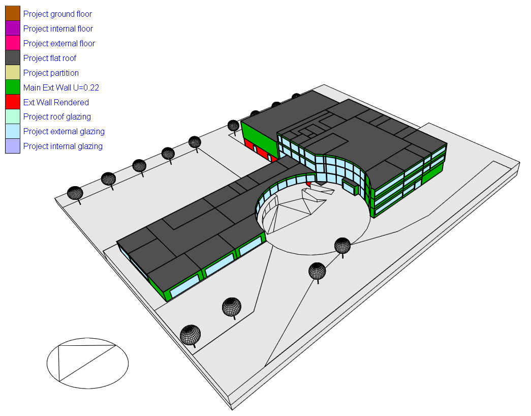
The screenshot below shows a typical external view of the constructions and glazing model data visualisation.
The legend on the left of the view provides the list of constructions and glazing components and the colour associated with each. In large models the list can be long and in this case you may find a scroll arrow at the bottom and/or top of the legend list to allow you to access the next/previous page.
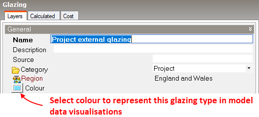
Tip: The Constructions and Glazing dialogs both allow you to select a colour to represent that component when applied to surfaces and openings. This is the colour used to shade surfaces and windows on this view.

As well as all the usual view control tools (orbit, zoom etc), some extra tools are provided to help you get the most out of the model data visualisation and these are described below. You will need to use either or both of the Surface removal or Section cut tools, described below, to view data for internal surfaces.
You can remove surfaces to allow internal surface data to be viewed by clicking with the mouse on any external or internal surface that you would like to be removed. You can use this tool to selectively expose data deep within a building without losing other data that you might also wish to view.
To restore a surface that was removed hold the <Ctrl> key down and click with the mouse again on the space where the removed surface should be.
To restore all removed surfaces press the <Esc> key.
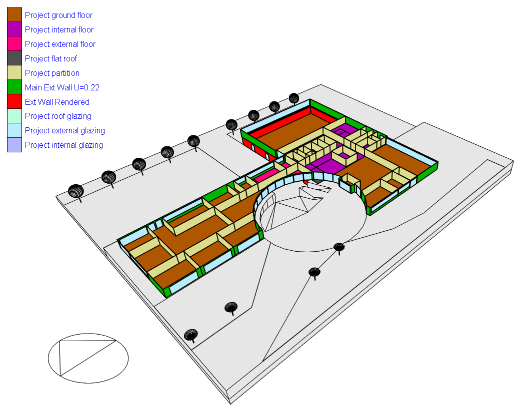
The example screenshot below shows the same model as above but with some of the roof surfaces removed as described above to reveal internal surfaces.

Note: Removing surfaces in this way only affects the model data visualisation view and does not affect the model itself.
The Section cut tool can be used to cut a slice through the model to allow internal data to be viewed. This tool can be especially useful for viewing data across a whole floor, or across a whole façade.
The example screenshot below shows the application of the section cut tool to allow the construction and glazing properties of internal constructions on the top floor to be viewed, as well as those for external surfaces.