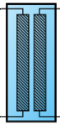
Fluid To Fluid Heat Exchanger
|
 HeatExchanger:FluidToFluid HeatExchanger:FluidToFluid
|
Used in:
- Plant and condenser loops, supply and demand side
|
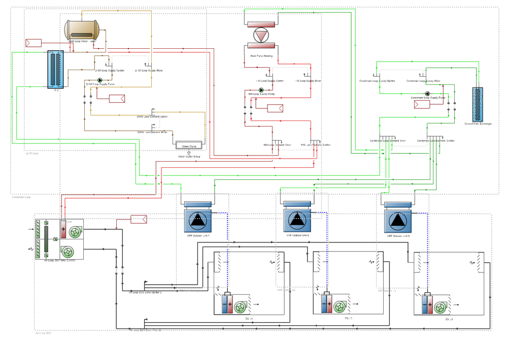
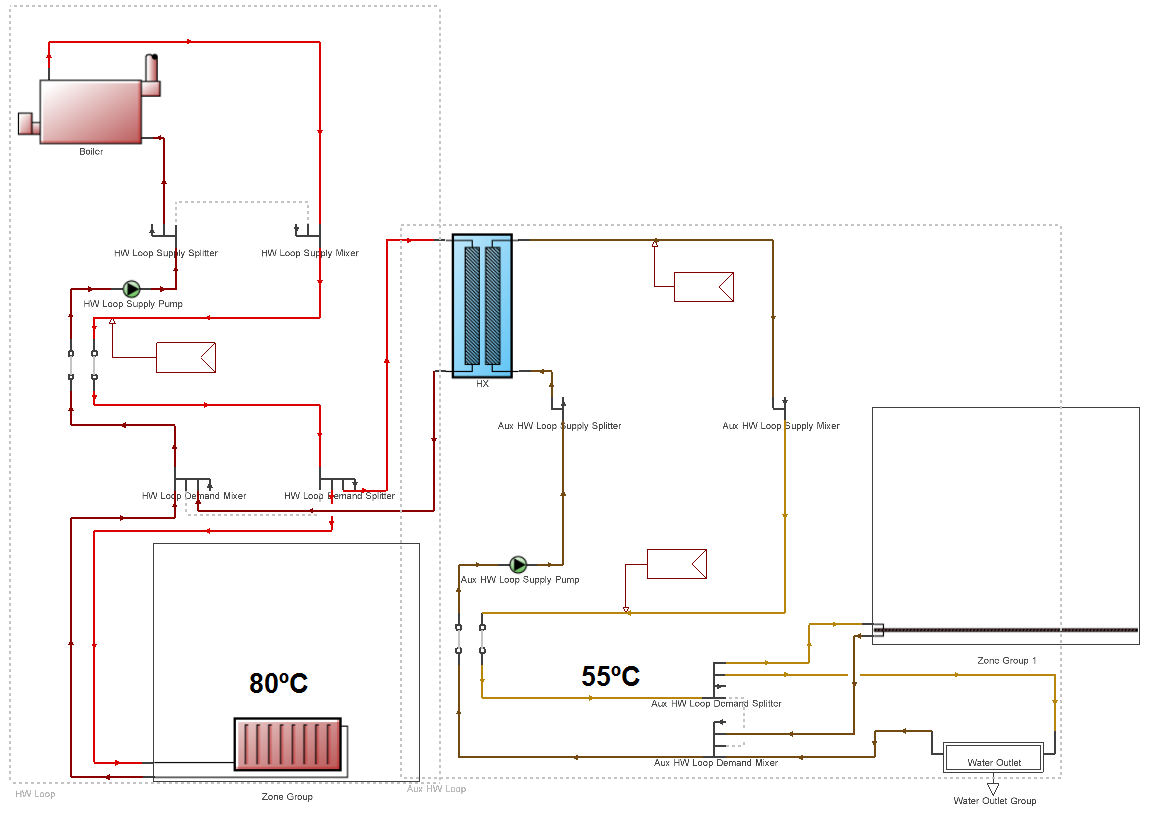
The fluid-to-fluid heat exchanger component (aka heat exchanger or HX) is designed to couple the supply side of one plant or condenser loop to the demand side of another plant or condenser loop. The heat exchanger is a fairly general component and can be configured for use in a situation where any two loops need to be connected together. The only constraints are that one side must be connected to the supply side of one loop and the other side connected to the demand side of a different loop.
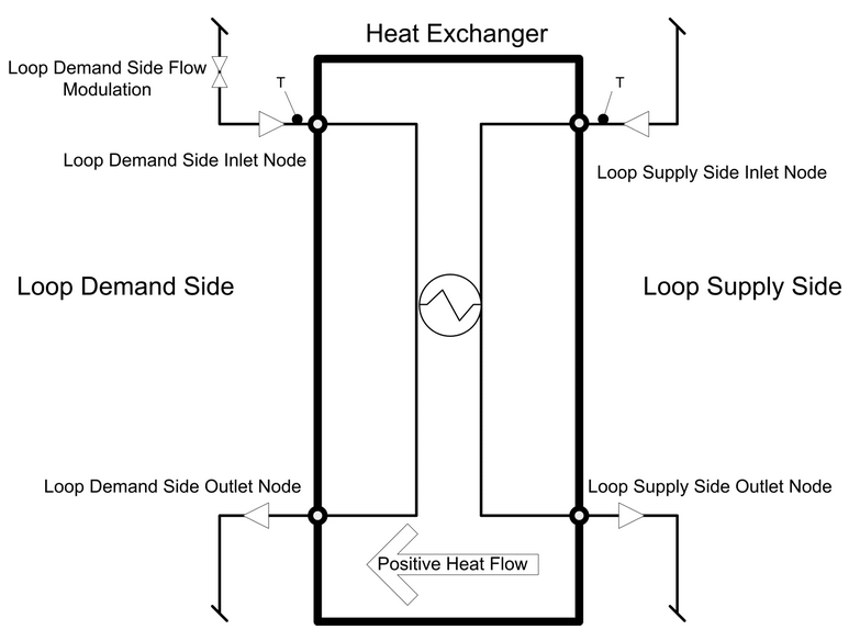
Plant Fluid to Fluid Heat Exchanger
Note: The adopted convention is that the heat exchanger must always be placed in a supply sub-loop.
Because the heat exchanger is intended to be generic, its two sides are distinguished by the nature of the loop side being connected. One side is called the “Loop Supply Side” to indicate that side of the heat exchanger connected to the supply side of a loop. The other side is called the “Loop Demand Side” to indicate it is connected to the demand side of a loop. The heat exchanger is intended to act as a supply component for the loop connected to it as the “Loop Supply Side” and as a demand component for the loop connected to it as the “Loop Demand Side”. From the point of view of the heat exchanger model itself, the Loop Demand Side fluid serves as the source/sink to supply heating/cooling to the fluid in the Loop Supply Side. The “Loop Supply Side” or “Loop Demand Side” connections of the heat exchanger are automatically enabled and disabled depending on which sub-loop is currently active to facilitate correct connection, i.e. to connect the supply side of the heat exchanger you must first navigate to the supply sub-loop in which the heat exchanger has been located and similarly navigate to the demand sub-loop of the loop to which the demand side of the heat exchanger is to be connected.
Various options are available for the heat exchanger component. The heat transfer between the two sides can be modelled using one of seven different models for different types of heat exchangers. Heat transfer is calculated and reported using a sign convention from chilled water applications where positive heat transfer indicates energy was extracted from the Loop Supply Side and added to the Loop Demand Side. A range of options are available for controlling the heat exchanger. One general type of control is “On/off” where the flow through the heat exchanger is either fully on or fully off. Another type of control is “Modulated” where the flow through the Loop Demand Side is controlled to try and meet a target setpoint or load on the Loop Supply Side.
 Applications
The fluid to fluid heat exchanger can be used for a wide variety of applications including chilled water, hot water, condenser, ground source, primary-secondary systems, etc.
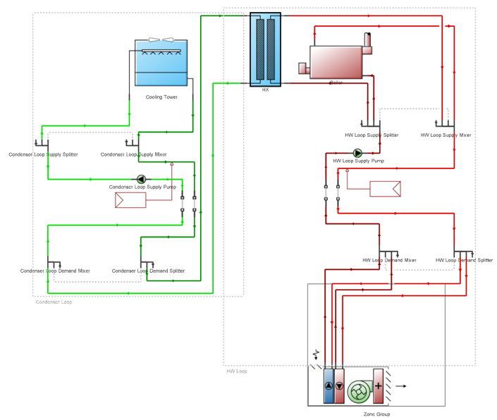
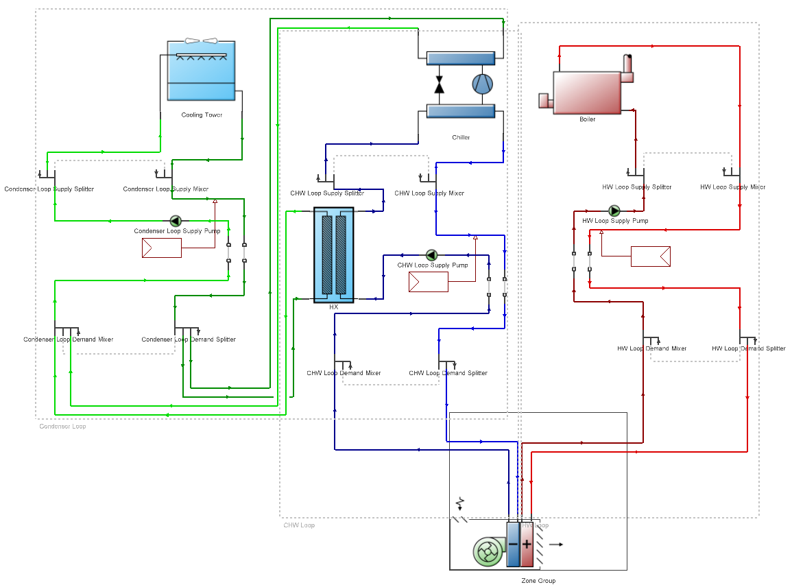
HX Example Application: Zone Ground Source Heat Pumps
HX Example Application: Waterside Economiser
HX Example Application: Air Source Heat Pump with Supplementary Heating
HX Example Application: Water Cooled VRF with Heat Recovery for DHW
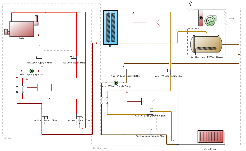
HX Example Application: Supply Hot Water at Different Temperatures from the same Boiler
General
Name
Enter a unique identifying name for this heat exchanger.
Operation
Availability schedule
Select an availability schedule to be used for supervisory control of the device. The heat exchanger is available for use whenever the schedule value is greater than zero. The heat exchanger is not available whenever the schedule value is zero or less.
Heat Exchanger Settings
Loop demand side design flow rate
This field specifies the design flow rate (in m3/s or gal/min) of the hydronic fluid passing through the heat exchanger on the Loop Demand Side. This field is autosizable. When autosized, this design flow rate is set to equal the design flow rate for the Loop Supply Side.
Loop supply side design flow rate
This field specifies the design flow rate (in m3/s or gal/min) of the fluid passing through the heat exchanger on the Loop Supply Side. This field is autosizable. When autosized, this design flow rate is set equal to the overall design flow rate of the loop that is connected. If a sizing factor is entered, then it is used to multiply this design flow rate.
Heat exchange model type
This alpha field identifies the nature of heat exchanger. Heat exchanger model type is specified by one of the following four key word choices:
- 1-Counter flow. Specifies a counter-flow shell and tube heat exchanger. The effectiveness is calculated using a counter-flow shell and tube heat exchanger correlation.
- 2-Cross flow both unmixed. Specifies a single-pass, cross-flow heat exchanger. The effectiveness is calculated using a cross-flow heat exchanger correlation for both streams unmixed.
- 3-Cross flow both mixed. Specifies a single-pass, cross-flow heat exchanger. The effectiveness is calculated using a cross-flow heat exchanger correlation for both streams mixed.
- 4-Cross flow supply mixed demand unmixed. Specifies a single-pass, cross-flow heat exchanger. The effectiveness is calculated using a cross-flow heat exchanger correlation for flow mixed on the Loop Supply side and flow unmixed on the Loop Demand Side.
- 5-Cross flow supply unmixed demand mixed. Specifies a single-pass, cross-flow heat exchanger. The effectiveness is calculated using a cross-flow heat exchanger correlation for flow unmixed on the Loop Supply side and flow mixed on the Loop Demand Side.
- 6-Parallel flow. Specifies a parallel-flow shell and tube heat exchanger. The effectiveness is calculated using a parallel-flow shell and tube heat exchanger correlation.
- 7-Ideal. Specifies an ideal heat exchanger. The effectiveness is set to 1 and the specified UA is ignored. The heat transfer rate is calculated as the maximum possible heat transfer rate.
Heat exchanger U-Factor times area value
This autosizable numerical field is used to specify the overall U-Factor Times Area (UA) (in W/K or Btu/h-°F) for use in the calculation of the heat exchanger effectiveness using the appropriate D-NTU correlation. If 7-Ideal is specified as the heat exchanger type, the effectiveness will be set to 1.0. When set to Autosize Heat Exchanger U-Factor Times Area Value is calculated based on an effectiveness of 1.0 where capacity is such that the temperatures in the plant sizing for the two loops can be maintained.
Control type
This option is used to specify how the heat exchanger is to be controlled during operation. Different applications for connecting two loops will require different control behavior and different control options are needed depending on the desired behaviour. There are a range of options to choose from:
- 1-Cooling differential on/off. This control mode is applicable to situations where the Loop Demand Side can provide useful cooling to the Loop Supply Side. This mode is similar to 8-Cooling setpoint on/off except that it ignores any cooling setpoint and its control is based only on the temperature difference between Loop Demand Side and the Loop Supply Side. The inlet temperatures must differ by more than the value set in the Minimum temperature difference to activate heat exchanger field for the heat exchanger to operate.
- 2-Uncontrolled on. This control mode is applicable to situations where the heat exchanger is passively running all the time and always transfers as much heat as possible between the fluid streams. Note that the HX will only request flow on the Loop Demand Side when there is non-zero flow into the heat exchanger on the Loop Supply Side.
- 3-Operation scheme modulated. This control mode is applicable to situations where the heat exchanger is controlled by a plant loop operation scheme. When using this control mode the heat exchanger must be listed in the list of equipment on the Plant Equipment Operation tab of the Plant or Condenser loop and it serves as a supply component. The operation scheme will dispatch a load request to the heat exchanger which it will try meet by conditioning the fluid stream connected as the Loop Supply Side. If the heat exchanger could exceed the load request, then the flow through the fluid stream connected as the Loop Demand Side will be modulated to just meet the load request.
- 4-Operation scheme on/off. This control mode is applicable to situations where the heat exchanger is controlled by a plant loop operation scheme. When using this control mode the heat exchanger must be listed in the list of equipment on the Plant Equipment Operation tab of the Plant or Condenser loop and it serves as a supply component. The operation scheme will dispatch a load request to the heat exchanger which it will use as an on/off signal to decide if the heat exchange should run or not. If it runs, it will run at full capacity and may exceed the load request.
- 5-Heating setpoint modulated. This control mode is applicable to situations where the Loop Demand Side can provide useful heating to the Loop Supply Side. For this control type, an SPM must be placed on the supply side outlet of the HX which is used to define the heating setpoint temperature for the HX. If the setpoint and inlet temperatures are such that heat exchanger could transfer heat from the Loop Demand Side to the Loop Supply Side to meet the heating setpoint, then the heat exchanger will run. The inlet temperatures must differ by more than the value set in Minimum temperature difference to activate heat exchanger for the heat exchanger to operate. If the heat exchanger could overshoot the setpoint, then the flow through the fluid stream connected as the Loop Demand Side will be modulated to just meet the setpoint.
- 6-Heating setpoint on/off. This control mode is applicable to situations where the Loop Demand Side can provide useful heating to the Loop Supply Side. For this control type, an SPM must be placed on the supply side outlet of the HX which is used to define the heating setpoint temperature for the HX. If the setpoints and inlet temperatures are such that heat exchanger could transfer heat from the Loop Demand Side to the Loop Supply Side to meet the heating setpoint, then the heat exchanger will run. The inlet temperatures must differ by more than the value set in Minimum temperature difference to activate heat exchanger for the heat exchanger to operate. If it runs, it will run at full capacity and may overshoot the setpoint.
- 7-Cooling setpoint modulated. This control mode is applicable to situations where the Loop Demand Side can provide useful cooling to the Loop Supply Side. For this control type, an SPM must be placed on the supply side outlet of the HX which is used to define the cooling setpoint temperature for the HX. If the setpoints and inlet temperatures are such that heat exchanger could transfer heat from the Loop Supply Side to the Loop Demand Side to meet the cooling setpoint, then the heat exchanger will run. The inlet temperatures must differ by more than the value set in Minimum temperature difference to activate heat exchanger for the heat exchanger to operate. If the heat exchanger could undershoot the setpoint, then the flow through the fluid stream connected as the Loop Demand Side will be modulated to just meet the setpoint.
- 8-Cooling setpoint on/off. This control mode is applicable to situations where the Loop Demand Side can provide useful cooling to the Loop Supply Side. For this control type, an SPM must be placed on the supply side outlet of the HX which is used to define the cooling setpoint temperature for the HX. If the setpoints and inlet temperatures are such that heat exchanger could transfer heat from the Loop Supply Side to the Loop Demand Side to meet the cooling setpoint, then the heat exchanger will run. The inlet temperatures must differ by more than the value set in Minimum temperature difference to activate heat exchanger for the heat exchanger to operate. If it runs, it will run at full capacity and may undershoot the setpoint. This control mode is suitable for use with waterside economisers.
- 9-Dual deadband setpoint modulated. This control mode is applicable to situations where the Loop Demand Side can provide either useful cooling or heating to the Loop Supply Side. For this control type, an SPM must be placed on the supply side outlet of the HX which is used to define the dual deadband setpoint temperature for the HX. If the setpoints and inlet temperatures are such that heat exchanger could transfer heat from the Loop Demand Side to the Loop Supply Side to meet the lower setpoint, then the heat exchanger will run. If the setpoints and inlet temperatures are such that heat exchanger could transfer heat from the Loop Supply Side to the Loop Demand Side to meet the high setpoint, then the heat exchanger will run. The inlet temperatures must differ by more than the value set in Minimum temperature difference to activate heat exchanger for the heat exchanger to operate. If the heat exchanger could overshoot the lower setpoint, or undershoot the higher setpoint, then the flow through the fluid stream connected as the Loop Demand Side will be modulated to just meet the deadband setpoint.
- 10-Dual deadband setpoint on/off. This control mode is applicable to situations where the Loop Demand Side can provide either useful cooling or heating to the Loop Supply Side. For this control type, an SPM must be placed on the supply side outlet of the HX which is used to define the dual deadband setpoint temperature for the HX. If the setpoints and inlet temperatures are such that heat exchanger could transfer heat from the Loop Demand Side to the Loop Supply Side to meet the lower setpoint, then the heat exchanger will run. If the setpoints and inlet temperatures are such that heat exchanger could transfer heat from the Loop Supply Side to the Loop Demand Side to meet the high setpoint, then the heat exchanger will run. The inlet temperatures must differ by more than the value set in Minimum temperature difference to activate heat exchanger for the heat exchanger to operate. If the heat exchanger runs, it will run at full capacity and may overshoot the lower setpoint or undershoot the higher setpoint.
Minimum temperature difference to activate heat exchanger
This value specifies the temperature tolerance used in control decisions in (DeltaC or DeltaF). Whenever the control logic needs to compare two temperatures, the value entered in this field is used as a threshold for comparisons.
Heat transfer metering end use type
This option specifies how the metering for heat transfer will be accounted in summary reports with respect to end uses. Although the heat exchanger consumes no energy that needs to be metered, there are also meters for heat transfers that apply to this heat exchanger model. The nature of the end use may vary depending on the application. The available choices are:
- 1- Free cooling,
- 2-Heat recovery,
- 3-Heat rejection,
- 4-Heat recovery for cooling,
- 5-Heat recovery for heating
- 6-Loop to loop.
Temperature Limits
Operation minimum temperature limit
When the Minimum temperature limit checkbox is checked this field is used to provide supervisory control of the heat exchanger. If either of the inlet temperatures are below this limit (°C or °F), the heat exchanger will not operate.
Operation maximum temperature limit
When the Maximum temperature limit checkbox is checked this field is used to provide supervisory control of the heat exchanger. If either of the inlet temperatures are above this limit (°C or °F), the heat exchanger will not operate.
Sizing Factor
Sizing factor
When the Sizing factor checkbox is checked this field can be used to modify the results of autosize calculations. This sizing factor is used for this heat exchanger and modifies sizing results by multiplying them by the factor entered here. This factor is applied to the Loop Supply Side Design Flow rate and in turn affects the heat exchanger UA and the loop demand side flow rate which are derived from that flow rate. This allows fine control over the size of the heat exchanger when using autosize in those fields.