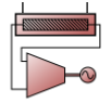

Generator:MicroTurbine
Used in:
- Hot water loop, supply side
- DHW loop, supply side
|
|
Generator:MicroTurbine |
Used in:
|
Micro Turbine generators are small combustion turbines that produce electricity on a relatively small scale (e.g., 25kW to 500kW). This model uses nominal performance at reference conditions along with several modifier curves to determine electrical power output and fuel use at non-reference conditions. Standby and ancillary power can also be taken into account. Energy recovery from exhaust air can be used to heat water. Similar to electrical power output, thermal power (heat recovery) output is calculated using nominal performance at reference conditions with modifier curves to account for variations at non-reference conditions.
This alpha field specifies a unique user-defined name to identify this generator. This is a required input.
Select the type of generator from the list:
This numeric field specifies the reference elevation relative to sea level (in m or ft). The value entered must be greater than or equal to -300.0m. The default value is 0.
Select the schedule that defines the times that the generator can operate.
Note: The way that this Availability schedule interacts with the Plant equipment operation, Scheme schedule for the attached Plant loop, depends on the Electric load centre, Generator operation scheme type setting as follows:
For the 1-Base load scheme type the generator availability schedule overrides the Plant equipment operation scheme schedule, so the generator can run whenever this schedule has a value > 0 regardless of the scheme schedule value.
For the 5-Follow thermal or 6-Follow thermal limit electrical scheme types, both this Availability schedule and the Plant equipment operation scheme schedule must have a value > 0 for the generator to operate.
This setting is used to define:
This numeric field specifies the full-load electrical power output of the generator (in W or Btu/h) at reference conditions. The reference conditions are defined via additional input fields for this object (see below). This is a required input, and the value entered in this field must be greater than zero.
This setting allows you to define the ratio of the rated thermal output to the rated electric output. This nominal ratio is only used for control and dispatch decisions and should be generally consistent with the more detailed performance input in the rest of this dialog, but it is not used in the component model. It is only used if the operation scheme is set on the Electric Load centre dialog is set to 5-Follow thermal or 6-Follow thermal limit electrical.
This numeric field specifies the minimum electrical power output (in W or Btu/h) at full-load conditions. The electrical power output of the generator is determined by multiplying the Reference electrical power output by the Electrical power function of temperature and elevation modifier curve. If the result is less than the numeric value specified in this input field, then the generator s electrical power output is reset to the minimum full-load value specified in this input field. The value entered in this field must be greater than or equal to zero.
This numeric field specifies the maximum electrical power output (in W or Btu/h) at full-load conditions. The electrical power output of the generator is determined by multiplying the Reference electrical power output by the Electrical power function of temperature and elevation modifier curve. If the result is greater than the numeric value specified in this input field, then the generator s electrical power output is reset to the maximum full-load value specified in this input field. The value entered in this field must be greater than zero.
Select a bi-quadratic performance curve that parameterises the variation of electrical power output as a function of the combustion air inlet temperature and elevation. The output of this curve is multiplied by the Reference electrical power output to give the full-load power output at a specific combustion air inlet temperature and elevation (i.e., at values different from the reference conditions). This curve should be normalized to have a value of 1.0 at the reference conditions, and the curve should be valid for the range of inlet air temperatures anticipated for the simulation period and for the actual elevation of the generator.
This setting specifies the standby electric power consumed by the generator (in W or Btu/h). The standby power is the electrical power consumed by the generator (e.g., air fans and controls) when the generator is available to operate but the generator electrical power output is zero (power output is not being requested by the electric load centre). The value specified for this field must be greater than or equal to zero. The default value is 0.
This numeric field specifies the ancillary electric power consumed by the generator (in W or Btu/h). The ancillary power is the electrical power consumed by other associated equipment (e.g., external fuel pressurization pumps) when the generator is operating. Specify this input as 0.0 if the Reference electrical power output and the Reference electrical efficiency using lower heating value input fields and associated modifier curves reflect the net electrical power output from the generator (i.e., ancillary power already deducted from the generator s gross electrical power output). A value greater than zero indicates that this electrical power is consumed whenever the generator is operating and will be deducted from the generator's overall electrical power output (Generator Produced Electric Power). The value specified for this field must be greater than or equal to zero. The default value is 0.
Select a quadratic performance curve that parameterises the variation of ancillary power as a function of the generator s input fuel mass flow rate (kg/s). The output of this curve is multiplied by the ancillary power to give the ancillary power at a specific fuel mass flow rate.
Select the type of fuel used by the generator from the list:
This numeric field specifies the lower heating value of the fuel used (in Btu/lb). The value specified for this field must be greater than zero but less than the specified Fuel higher heating value (below). The default value is 45,450 kJ/kg.
This numeric field specifies the higher heating value of the fuel used (in Btu/lb). The value specified for this field must be greater than zero and greater than the specified Fuel lower heating value (above). The default value is 50,000 kJ/kg.
This numeric field contains the electrical efficiency of the generator at reference conditions, based on the lower heating value of the fuel. The electrical efficiency is the electric power output divided by the fuel energy consumption rate (LHV basis). The reference conditions are defined via additional input fields for this object (see below). This is a required input, and the value entered in this field must be greater than zero and less than or equal to 1.0.
Select a quadratic or cubic performance curve that parameterises the variation of electrical efficiency as a function of the combustion air inlet temperature. The output of this curve is multiplied by the Reference electrical efficiency using lower heating value to give the full-load electrical efficiency at specific combustion air inlet temperatures (i.e., at inlet air temperatures different from the Reference combustion air inlet temperature). This curve should be normalized to have a value of 1.0 at the Reference combustion air inlet temperature, and the curve should be valid for the range of inlet air temperatures anticipated for the simulation period.
Select a quadratic or cubic performance curve that parameterises the variation of electrical efficiency as a function of the generator s part-load ratio (part-load ratio is the actual electrical power output divided by the full-load electrical power output at the current operating conditions). The output of this curve is multiplied by the Reference electrical efficiency using lower heating value and the output of the Electrical Efficiency Function of Temperature curve to give the electrical efficiency at specific part-load and combustion air inlet (temperature) conditions. This curve should be normalized to have a value of 1.0 when the generator s part-load ratio is 1.0, and the curve should be valid for the range of part-load ratios anticipated for the simulation period.
This numeric field specifies the reference temperature for the combustion inlet air (in °C or °F). The default value is 15°C.
This numeric field specifies the reference humidity ratio for the combustion inlet air in kgWater/kgDryAir. The value specified for this field must be greater than zero. The default value is 0.00638 (kgWater/kgDryAir).
This numeric field is the reference exhaust air mass flow rate (in kg/s or lb/s). Entered values must be greater than zero.
This numeric field is the exhaust air outlet temperature at nominal (reference) conditions (in °C or °F).
Select a quadratic or cubic performance curve that parameterises the variation of exhaust air flow rate as a function of the combustion air inlet temperature. The output of this curve is multiplied by the Reference exhaust air mass flow rate to give the exhaust air mass flow rate at non-reference combustion air inlet temperatures. This curve should be normalized to have a value of 1.0 at the Reference combustion air inlet temperature, and the curve should be valid for the range of inlet air temperatures anticipated for the simulation period.
Select a quadratic or cubic performance curve that parameterises the variation of exhaust air flow rate as a function of the generator s part-load ratio (part-load ratio is the actual electrical power output divided by the full-load electrical power output at the current operating conditions). The output of this curve is multiplied by the Reference exhaust air mass flow rate to give the exhaust air mass flow rate at specific part-load operating conditions. This curve should be normalized to have a value of 1.0 when the generator s part-load ratio is 1.0, and the curve should be valid for the range of part-load ratios anticipated for the simulation period.
Select a quadratic or cubic performance curve that parameterises the variation of exhaust air outlet temperature as a function of the combustion air inlet temperature. The output of this curve is multiplied by the Nominal exhaust air outlet temperature to give the exhaust air temperature at non-reference combustion air inlet temperatures. This curve should be normalized to have a value of 1.0 at the Reference combustion air inlet temperature, and the curve should be valid for the range of inlet air temperatures anticipated for the simulation period.
Select a quadratic or cubic performance curve that parameterises the variation of exhaust air outlet temperature as a function of the generator s part-load ratio (part-load ratio is the actual electrical power output divided by the full-load electrical power output at the current operating conditions). The output of this curve is multiplied by the Nominal exhaust air outlet temperature to give the exhaust air temperature at specific part-load operating conditions. This curve should be normalized to have a value of 1.0 when the generator s part-load ratio is 1.0, and the curve should be valid for the range of part-load ratios anticipated for the simulation period.
This field is used to choose between different modes of controlling the mass flow rate of water being heated by energy recovered from exhaust air. There are two options available:
This numeric field is the reference heat recovery (volumetric) water flow rate (in m3/s or gal/min). Entered values must be greater than zero.
This numeric field specifies the reference temperature for the inlet water to the heat recovery heat exchanger (in °C or °F).
This numeric field specifies the thermal efficiency (heat recovery to water) at reference conditions, based on the lower heating value of the fuel. The thermal efficiency is the thermal power output (to water) divided by the fuel energy consumption rate (LHV basis). The reference conditions are defined via additional input fields for this object. This value must be from 0.0 to 1.0. The default value is 0.
This numeric field specifies the minimum (volumetric) water flow rate through the heat recovery heat exchanger (in m3/s or gal/min). The minimum input value is 0.0. The default value is 0.
This numeric field specifies the maximum (volumetric) water flow rate through the heat recovery heat exchanger (in m3/s or gal/min). The minimum and default input values for this field are 0.0. The maximum heat recovery water flow rate must be greater than or equal to the minimum heat recovery water flow rate.
This field sets the maximum water temperature (in °C or °F) that this generator can produce via heat recovery. This temperature limit puts an upper bound on the recovered heat and limits the max temperatures leaving the component. As temperatures in the water loop approach this maximum temperature, the temperature difference between the entering water and the surfaces in generator s heat recovery heat exchanger becomes smaller. For the given heat recovery flow rate and that temperature difference the amount of heat recovered will be reduced, and eventually there will be no heat recovered when the entering water temperature is equal to the maximum temperature specified by the user in this field. The amount of heat recovered will diminish if the inlet water temperature approaches the maximum temperature, and this will show up in the reporting.
Select a bi-quadratic performance curve that parameterises the variation of thermal efficiency as a function of the combustion air inlet temperature and elevation. The output of this curve is multiplied by the Reference thermal efficiency using lower heating value to give the full-load thermal efficiency at a specific combustion air inlet temperature and elevation (i.e., at values different from the reference conditions). This curve should be normalized to have a value of 1.0 at the reference conditions, and the curve should be valid for the range of inlet air temperatures anticipated for the simulation period and for the actual elevation of the generator.
Select a quadratic or cubic performance curve that parameterises the variation of heat recovery to water (thermal power output) as a function of the generator s part-load ratio (part-load ratio is the actual electrical power output divided by the full-load electrical power output at the current operating conditions). The output of this curve is multiplied by the steady-state heat recovery at the current combustion inlet air temperature and elevation to give the heat recovery rate (thermal power output) at specific part-load operating conditions. This curve should be normalized to have a value of 1.0 when the generator s part-load ratio is 1.0, and the curve should be valid for the range of part-load ratios anticipated for the simulation period.
Select a quadratic performance curve that parameterises the variation of heat recovery to water (thermal power output) as a function of the inlet water temperature. The output of this curve is multiplied by the steady-state heat recovery at the current combustion inlet air temperature and elevation to give the heat recovery rate (thermal power output) at non-reference inlet water conditions. This curve should be normalized to have a value of 1.0 at the Reference inlet water temperature, and the curve should be valid for the range of inlet water temperatures anticipated for the simulation period.
Select a quadratic performance curve that parameterises the variation of heat recovery to water (thermal power output) as a function of the heat recovery water flow rate. The output of this curve is multiplied by the steady-state heat recovery at the current combustion inlet air temperature and elevation to give the heat recovery rate (thermal power output) at non-reference heat recovery water flow rates. This curve should be normalized to have a value of 1.0 at the Reference heat recovery water flow rate, and the curve should be valid for the range of water flow rates anticipated for the simulation period.
Select a bi-quadratic performance curve that parameterises the variation of heat recovery water flow rate as a function of the inlet water temperature and net electrical power output. This data is only used if the Heat recovery water flow operating mode is 2-Internal control. The output of this curve is multiplied by the Reference heat recovery water flow rate to give the water flow rate at the specific inlet water temperature and net power operating conditions. This curve should be normalized to have a value of 1.0 at the reference conditions, and the curve should be valid for the range of inlet water temperatures and net electrical power output anticipated for the simulation period.