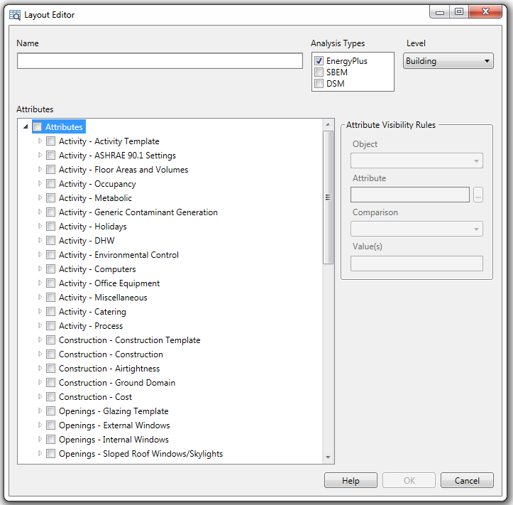
The Layout Editor dialog allows user-defined custom Layouts to be set up for use alongside the pre-defined layouts provided with the software. The Layout editor can be launched from the management dialog via the Manage Layouts > New and Edit buttons. On first opening the Layout Editor dialog will look something like this:
There are 4 areas of data to be entered on the dialog:
These 4 areas are covered in more detail below.
When creating a new Layout, the Analysis type is set by default to match that of the current model's Analysis type (typically EnergyPlus, SBEM or DSM) and the Level is set to Building. The list of available attributes is based on the Analysis type and Level selections and will change when different combinations of Analysis types and level are selected.
Enter a descriptive identification for the layout. This will be displayed on the list of Layouts on the main Model Data Grid View Management dialog.
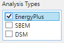
Select one or more analysis types to define which are compatible for the layout being defined. For example if your layout should only be available for EnergyPlus models for then check that checkbox only. In this case the Layout will appear in the Layout list on the main Model data grid view management dialog for models where the Analysis type is set to EnergyPlus. However, if your model is located in the UK and the Analysis type for your model is set to SBEM or DSM then this layout won't appear in the Layout list.
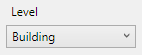
Select the model object the layout will apply to. Options are:
For example if you select the Zone level, the layout will display data for zones, i.e. each row in the model data grid view will be for a zone. In this case the attributes specified for each zone are defined as described below.
The attributes to be displayed as columns in the model data grid view are defined by making appropriate selections in the list of attributes by checking the required attributes.
The attributes list is grouped into categories based on the model data tab in which it appears: Activity, Construction, Lighting, Outputs, CFD etc. The tree view nodes can be expanded to reach the required attributes which can have their respective checkboxes checked to select the attribute to be included with the layout. See below.
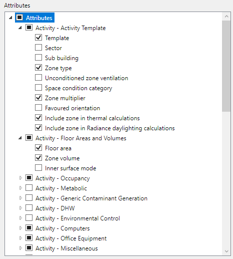
The attributes displayed in the list depends on the Analysis types and model object Level selected (see above).
If the Layout Editor was launched for an existing Layout via the Edit button from the Layout management group then the attributes to be displayed will have their respective check boxes checked.
To enhance the information presented on the data grid, some additional read-only attributes are included in the list depending on the data level. If custom attributes are available for the selected level they will appear at the bottom of the attributes list. Custom Attributes will always appear in the data grid, unless an attribute visibility rule has been defined to hide them in certain circumstances.
Clicking “OK” will create/update a new/existing Layout.
Clicking “Cancel” will return to Layout Management without saving changes.
When you select an attribute in the list on the left of the dialog, the settings in the Attribute Visibility Rules group on the right of the dialog are enabled and you can define a rule to customise the visibility of that attribute in the data grid. Visibility rules are set up to ensure that attributes are only displayed in the model data grid view where appropriate. Visibility rules work through a simple comparison using an attribute from a level higher up the hierarchy than the objects being displayed. There are 2 types of rules:

For both types of rule you may need to refer to some attribute option lists to help you define the visibility rules. Some commonly used attribute settings are listed below under Attributes Commonly used in Visibility Rules.
The Object selection determines which model object level will be used as the basis for the rule. Note that only levels "above" the level specified in the Layout level are available. For example if the layout Level is set to Zone then the only Object options allowed are Block, Building and Site.
The Attribute to be used in the visibility rule can be chosen by clicking the browse button "…" to display the Attribute Browse dialog:
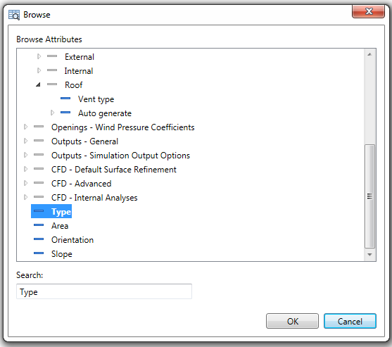
Attributes in this tree view are based on the selected model Object selected and the Analysis types as described above.
Custom attributes (if applicable for the selected model Object) are found at the bottom of the tree view.
The comparison operator for the rule. Currently available options are:
The value to compare the chosen attribute value against. A range of values can be specified by separating with commas. E.g. 1,2,10. So, for example, for Model Object “Site” for attribute “Analysis Type” with a comparison on “=” and a value = “1,2,10” the rule will be passed if the current model’s Analysis type is 1-EnergyPlus, 2-SBem or 10-DSM.
A rule applied using a high level attribute will impact the visibility of the attribute for all objects in the grid, i.e. the column won’t appear in the data grid. The example below shows the how the rule for the Occupancy density attribute is set up, based on the value of the Occupancy method.
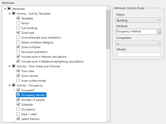
Note: Column visibility rules use Site or Building level attributes such as Analysis type (a site level attribute) or building model options. An exception would for a layout set up to list building level data for multiple buildings on the site in which case building attributes not would be an option and only site level attributes could be used.
Rules applied at a lower level allow the visibility attributes to be controlled on a per object basis. For example the screenshot below shows a case where data grid cells are shown for the Roof Glazing type attribute for openings where the opening’s parent Surface type has a value of 2, i.e. it is a pitched roof:
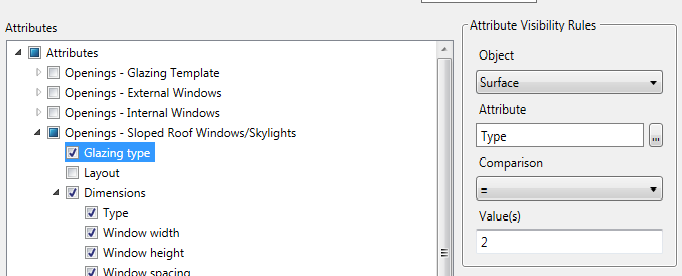
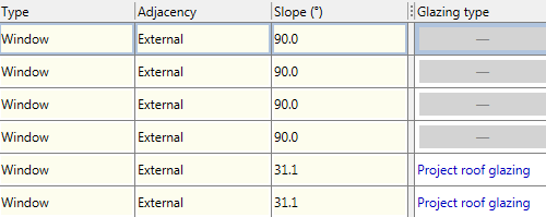
This rules results in a grid view similar to that shown below where the rule applied only allows the Roof glazing type to be shown for the 2 pitched roof windows:
The Analysis type is a site level attribute set on the Display tab of the Model option options dialog defining the purpose of the analysis. It controls which user interface items, data, calculations and outputs are available.
Analysis type can be used for controlling the availability of entire layouts through use of the Analysis types checkboxes as described above or individual attributes through the Attribute visibility rules.
The most common Analysis types are:
It can be useful to show/hide opening level attributes based on the parent surface type. For example displaying Glazing type for surfaces of type 3 (walls). See above under Cell visibility rules. The full list of surface types used internally by DesignBuilder is as follows: