
The Moisture transfer component provides data for either HAMT or EMPD or both. It can be selected from the Materials dialog from under the Moisture Transfer header at the bottom of the General tab.
DesignBuilder is provided with a database of moisture transfer properties for a small range of representative materials. The database includes properties for both HAMT and EMPD calculation methods. The HAMT database is derived from IEA Annex 24 c.1996.
For details on the HAMT algorithms used within EnergyPlus see the Combined Heat and Moisture Transfer (HAMT) Model section in the Engineering Reference.
Note: Moisture transfer data provided in the literature tends to be approximate, much more so than for thermal properties. This is due to large variations in these properties that have been measured in lab tests.
Enter a unique name for this set of moisture transfer data.
The <All> category is presently the only option.
You can choose to enter data for EMPD and/or HAMT. Select from:
When either of the 1-EMPD or 3-EMPD and HAMT options are selected the EMPD tab will be shown. If either of the 2-HAMT or 3-EMPD and HAMT options are selected the following tabs will be shown:
The Effective Moisture Penetration Depth (EMPD) moisture model will be used when the appropriate EMPD moisture materials are specified and the Moisture transfer simulation method is one the EMPD options. When the EMPD option is being used, data on this tab is used to describe the moisture material properties that are used in the 5-Moisture Penetration Depth Conduction Transfer Function solution algorithm. The EMPD algorithm is a simplified, lumped moisture model that simulates moisture storage and release from interior surfaces.
The model uses convective mass transfer coefficients that are determined by existing heat and mass transfer relationships, e.g. the Lewis relation. The EMPD model includes two fictitious layers of material with uniform moisture content: a surface layer, which accounts for short-term moisture buffering, and a deep layer, which accounts for more slowly responding moisture buffering. The model calculates the moisture transfer between the air and the surface layer and between the surface layer and the deep layer. This moisture transfer impacts the zone humidity, and also impacts the zone temperature through latent-to-sensible conversion from the heat of adsorption.
The vapour diffusion resistance factor is the resistance to water vapour diffusion relative to the resistance to water vapour diffusion in stagnant air. In other words, equals 1 for air, and is generally greater than 1 for building materials. The equation for µ is:
where δperm,air is the permeability of water vapour in air [kg/m-s-Pa], and δperm is the permeability of water vapour in the material. The permeability of water vapour in air can be estimated as:
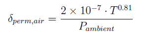
where T is the temperature [C] and Pambient the ambient atmospheric pressure [Pa].
This field is used to enter the effective moisture penetration depth of the material layer. Units for this parameter are m or ft.
The Surface layer penetration depth is the fictitious thickness of the surface layer (in m or in), and is used to calculate the volume of material that participates in short-term moisture transfer and storage. This layer has a uniform moisture content, and can be considered a lumped-capacitance. The penetration depth is based on the amount of material that interacts with the zone air when subject to a cyclic relative humidity variation. It also impacts the mass transfer resistance between the zone air and this layer, with thinner depths resulting in lower mass transfer resistances (ref: Effective Moisture Penetration Depth (EMPD) Model in the Engineering Reference). For this reason very small values can lead to instabilities depending on the timestep. The surface penetration depth can be estimated with the following equation:

where:
δperm = water vapor permeability in the material, kg/m-s-Pa (see Vapour diffusion resistance factor above)
Psat = saturated vapor pressure at some nominal temperature, Pa
τsurf = cycle period of typical RH variations, s. 24 hours (86,400 s) is often used.
ρmaterial = dry density of material, kg/mˆ3
du/dϕ = slope of moisture soprtion curve, abϕb-1 + cdϕd-1
If this field is set to autocalculate, the above equation will be used to calculate the surface layer penetration depth assuming a surf of 24 hours. To use a period different than 24 hours, the equation above can be used to calculate the penetration depth based on a different value of surf . The penetration depth can also be entered as an empirical value, as in Woods and Winkler, 2016. If calculating dEMPD,surf , the assumed value of τsurf should not be less than 4x the simulation timestep to ensure an accurate and stable solution.
The Deep layer penetration depth is the fictitious thickness of the deep layer (in m or in), and is used to calculate the volume of material that participates in long-term moisture transfer and storage. This layer has a uniform moisture content, and can be considered a lumped-capacitance. The deep penetration depth is based on the amount of material that interacts with the surface layer when subject to cyclic relative humidity variation. The deep penetration depth can be estimated with the following equation:
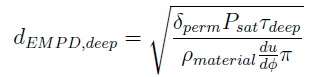
Each term is the same as for the surface layer, except that the cycle period is different. This is usually on the order of weeks for the deep layer. If this field is set to autocalculate, the above equation will be used to calculate the deep layer penetration depth assuming a deep of three weeks. To use a period different than 3 weeks, the equation above can be used to calculate the penetration depth based on a different
value of deep. The penetration depth can also be entered as an empirical value, as in Woods and Winkler, 2016.
The Coating Layer Thickness (in m or in) adds an additional resistance between the surface layer and the zone and represents a thin coating, such as paint, plaster, or other wall coverings. This input is optional, and an input of zero implies no coating.
The vapour diffusion resistance factor of the coating is the coating’s resistance to water vapour diffusion relative to the resistance to water vapour diffusion in stagnant air (see Vapour diffusion resistance factor section above). An input of zero implies no coating.
The next four fields, coefficients “a”, “b”, “c”, and “d”, help define the sorption isotherm curve used for building materials under equilibrium conditions. They are used to define the relationship between the material’s moisture content and the surface air relative humidity (ref: Effective Moisture Penetration Depth (EMPD) Model in the Engineering Reference):
U = aφb + cφd
where:
a,b,c,d = Coefficients to define the relationship between the material’s moisture content and the surface air relative humidity
U = Moisture content defined as the mass fraction of water contained in a material (kg/kg or lb/lb)
φ = Surface air relative humidity [0 to 1].
The next four fields are dimensionless coefficients:
The porosity of a material is the maximum fraction, by volume, of a material that can be taken up with water. The units are m3/m3 or ft3/ft3.
Enter the initial water content ratio (in kg/kg or lb/lb). For the HAMT solution algorithm the initial water content is assumed to be distributed evenly through the depth of the material.
The Sorption Isotherm data relates the moisture, or water content of a material with the relative humidity (RH). The water content is expected to increase as relative humidity increases, starting at zero content at 0.0 RH fraction and reaching a maximum, defined by the porosity, at 1.0 RH fraction, which corresponds to 100% relative humidity. Relative humidities are entered as fraction ranging from 0.0 to 1.0. These two extremes (0.0 and 1.0) are automatically set by the HAMT solution. However, if they are entered they will be used as extra data points. Data should be provided with increasing RH and moisture content up to as high an RH as possible to provide a stable solution.
One possible reason for the following error message may be that a material has a very rapid increase in water content for a small change in RH, which can happen if the last entered water content point is at a low RH and the material has a very high porosity.
** Warning ** HeatAndMoistureTransfer: Large Latent Heat for Surface ROOF
A maximum of 25 coordinates can be specified.
The relative humidity of the nth coordinate. The relative humidity is entered as fraction, not in percent.
The Moisture content of the nth coordinate. The units are kg/m3 or lb/ft3
The suction data relates the liquid transport coefficient, under suction, to the water content of a material. A data point at zero water content is required. The liquid transport coefficient at the highest entered water content value is used for all liquid transport coefficient values above this water content. These coefficients are used by HAMT when the rain flag is set in the weather file.
A maximum of 25 points can be specified.
The moisture content of the xth point. The units are kg/m3 or lb/ft3.
The Liquid Transport Coefficient of the xth point. The units are m2/s or ft2/s.
The redistribution data relates the liquid transport coefficient to the water content of a material under normal conditions. A data point at zero water content is required. The liquid transport coefficient at the highest entered water content value is used for all liquid transport coefficient values above this water content. These coefficients are used by the Heat and Moisture Transfer algorithm when the rain flag is NOT set in the weather file.
A maximum of 25 points can be specified.
The moisture content of the nth point. The units are kg/m3 or lb/ft3.
The Liquid transport coefficient of the nth point. The units are m2/s or ft2/s.
The MU data relates the vapor diffusion resistance factor (dimensionless) to the relative humidity as fraction (RH). A data point at zero RH is required. The vapor diffusion resistance factor at the highest entered relative humidity (RH) value is used for all vapor diffusion resistance factor values above this RH. The relative humidity maximum value in fraction is 1.0.
A maximum of 25 pairs can be specified.
The moisture content of the nth pair. The relative humidity is entered as fraction, not in percent.
The Liquid transport coefficient of the nth pair.
The thermal data relates the thermal conductivity of a material to the moisture or water content. A data point at zero water content is required. The thermal conductivity at the highest entered water content value is used for all thermal conductivity values above this water content.
A maximum of 25 coordinates can be specified.
The moisture content of the nth coordinate. The units are kg/m3 or lb/ft3.
The Thermal conductivity of the nth coordinate. The units are W/m-K or Btu-in/h-ft-°F.