Openings tab in model data
External vents are typically used for modelling airflow through external vent openings for the purposes of providing fresh air and/or zone cooling. They are only used when the Calculated natural ventilation model option is selected. When using Scheduled natural ventilation external vents should, in general, not be added to the model since, in this case, outdoor airflow is defined explicitly at zone level and the vent settings cannot be accessed to define the conductance and texture.
Vents can be added to the model by navigating to the appropriate surface and either:
Setting the Auto generate option and settings the Preferred width and height options. In this case a vent will be positioned under each of the windows (if the vent spacing is the same as the window spacing), or,
Alternatively, for more control over the placement position of the vents, you can draw the vents using the Draw vent command. Note that on surfaces where custom openings have been defined, any changes to vent layout model data on the Opening tab is ignored.
Note: if you have drawn custom vents at the surface level then these will be used even if the Auto generate checkbox is not checked. The Auto generate checkbox only controls the automatic generation of vents, not their use in the calculations.
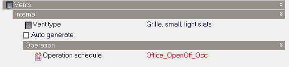
The properties of the vent are defined by the selection of the vent type:
Select the vent component that holds additional property data on the vent type such as the construction, texture and discharge coefficient to be applied.
The additional vent model data that can be added is described under:
Important Note: The external vent operation settings are only made available for editing when the Natural Ventilation > On checkbox is checked on the HVAC tab.
Roof vents are defined as any vents placed on an external pitched or flat roof surface. The vent type for roofs is defined separately under the Roof header.
Although roof vents have a separate vent type selection you should use the same operation schedule as for External vents to define simulated vent opening availability. This data can be accessed under the Vents > External > Operation header.
Regardless of the Natural ventilation model option selected, data on internal vents can always be accessed. In this case the properties of the selected vent component(s) define the resistance to heat conduction and airflow (see details below under Vent Modelling).
Note: Internal vent data is not available at zone level to avoid ambiguity when different settings are made in adjacent zones. Surface level internal vent settings are generally inherited from block level, however settings for inter-block vents are inherited from the building level. For details on these rules see: Zone Level Data for Internal Surfaces.
Otherwise the same comments made above for External vents also apply to Internal vents.
Calculated Natural Ventilation (Simulations only)
Each vent is modelled using:
Scheduled Natural Ventilation (and Heating and Cooling Design Calculations)
Each vent is modelled using:
Holes are modelled in a similar way to vents with some exceptions:
Calculated Natural Ventilation (Simulations only)
Each hole is modelled using an EnergyPlus sub-surface and an airflow connection:
Scheduled Natural Ventilation (and Heating and Cooling Design Calculations)
Each hole is modelled using an EnergyPlus sub-surface as follows: