Import 2-D Drawing
DXF and other bitmap-type drawing data formats can be imported in the form of 2-D floor plan or elevation layout drawings. These
can be used to trace block perimeters, partitions and façades as a fast way to enter the model geometry. A typical process is as follows:
- Create new dsb site file, select location etc.
- Import floor plan data (described below).
- Go to block level and draw partitions by tracing over the drawing data.
- Import other DXF floor plans for other stories
if necessary.
The process of importing elevation drawings for drawing opening often takes place after the main block geometry definition and partitioning has been completed as follows:
- Import elevation DXF data to the ground plane (you cannot import 2-D drawing data directly to any other plane).
- Move the DXF object to a wall surface by selecting it and using the Move command.
- Go to surface level and trace windows, doors and any other openings by snapping to the DXF data.
It is also possible to use elevation drawings to create the original block form as described below.
Note: It is necessary to switch on the Show imported 2-D drawing at zone and surface levels Display model option on when using an imported elevation to show the position of windows, doors etc at surface level.
Tip: When a 2-D drawing is loaded, sometimes the drawing data can come between the mouse cursor and objects to be accessed. In this case, pressing the <Shift> key while left mouse clicking allows the drawing to become "transparent" to any clicks, making it easier to access model objects such as blocks and openings, which are behind the drawing data.
 Using an Elevation Drawing to Create a Block with Openings
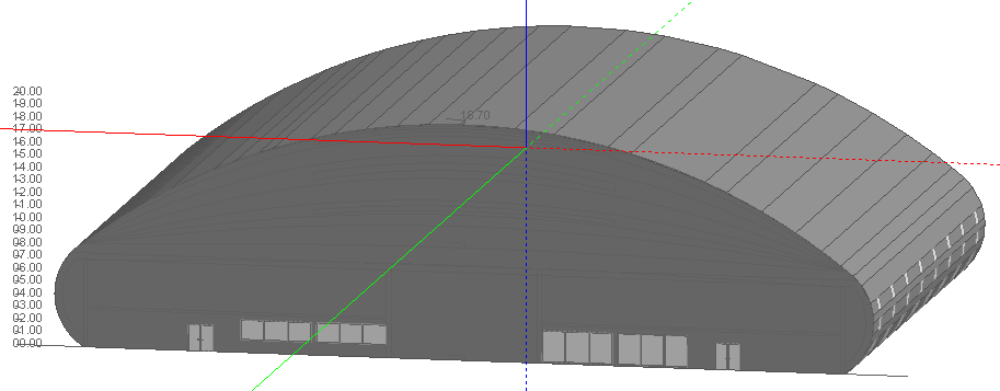
Elevation drawings can also be used for creating horizontally extruded blocks of complex section such as the aircraft hanger elevation drawing below, placed on an outline block ready to create a horizontally extruded block shape.
Using the Add surface tool, trace the outline of the hanger external façade:
The Cutting tool can be used to remove the original rectangular part of the outline block. The image below shows the outline block from the other side with the rectangular part of the outline block removed so we can see the drawing coplanar with the block facade:
The hanger outline block has now been converted to a building block and once navigated to surface level we are ready to use the drawing to help trace the windows and doors onto the surface:
Note: Make sure that the correct surface is selected when navigating to surface level
Completed hanger block with windows and doors drawn at building level:
 More information on Importing floor plans can be found in the Importing drawing files tutorial
Import Drawing File Wizard
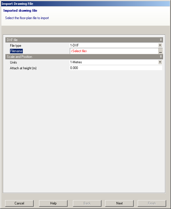
You can import 2-D DXF floor plan files created in AutoCAD or other CAD programs or the other bitmap-based drawing formats listed below. To start the process click on the Files > Import > Import 2-D drawing file menu command. This starts a the Import Drawing File Wizard.
With the import wizard open, select the File type to import. You can select from:
- 1-DXF - 2-D CAD data. This option allows you to snap to the end-points of the DXF line segments, the other bitmap-based formats below do not allow snapping.
- 2-PDF - PDF drawing file (single page). Note only PDF files with a single page will import successfully into DesignBuilder.
- 3-BMP - Bitmap drawing file.
- 4-JPG - JPEG drawing file.
- 6-GIF - GIF drawing file.
- 7-TIFF - TIFF drawing file.
When you have selected the file type then select the file by clicking into the 'Filename' control. Click on the ellipsis button to open the file
browser dialogue box.
Once the floor plan has been imported you can add blocks by tracing over the external
perimeter corners of the floor plan.
DXF File types
While on the Import drawing file wizard, if you selected a DXF file you must then select the units used in the DXF file from the Units drop list. You should be able to find this out from the creator of the CAD model - you are likely to get 'out of range' errors if you get it wrong. For example the CAD drawing may have been defined in millimetres and if you have selected metres as the units, when DesignBuilder tries to read the floor plan everything is 1000x too big and meters become kilometres! The DesignBuilder modeller has a range of several hundred metres and if any data falls outside this, the 'out of range' error occurs.
DesignBuilder supports ASCII DXF, and not binary DXF format. You can covert binary files to ASCII using a utility such as DDS-CAD Viewer.
Tip: DesignBuilder is not able to import DXF files that are already open in other applications, so if you have been checking the DXF file that you plan to import in AutoCAD or other CAD tool, you should make sure to close the file before attempting to import it into DesignBuilder.
You must also set
the attachment height at which the 2-D DXF floor plan will be attached in the DesignBuilder model. The
DXF data can be moved around the model once it is imported, so you do
not need to know the exact attachment height at this stage - you can import the DXF
data at zero height and move it to the correct location using the Move
command. Click on the 'Next' button to set up layer visibility:
You can use these controls to switch off unnecessary layers in the DXF
data. As you check/uncheck the checkboxes you will see the effect of the
change in the Edit view under the Wizard. Click on the 'Finish' button
to import the data:
At the building level, you can select,
move and delete DXF
data. When you select DXF data, you may need to zoom in to make the selection.
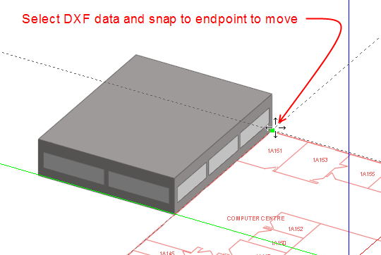
You can move DXF file in 3-D and snap the data to the edges of blocks or end-points of construction lines:
Move the DXF data on top of the existing block and snap to an edge end-point:
When you have imported the DXF data you can use the Measure tool to
check that the dimensions are correct.
Import DXF floor plans for other stories
if necessary. Note that only one set of DXF data can be imported at a
time. Once the CAD data has been imported into the model, the source DXF
file is no longer needed by DesignBuilder and can be moved or deleted.
Editing DXF data
Once the DXF data has been imported to the model, it must be selected to allow these operations:
- Move - move the DXF data
- Delete - delete the DXF data (not the source file itself).
Also the Set X-axis for imported DXF and Scale DXF drawing menu commands are available from the Edit menu when DXF data is loaded.
Set X-axis for imported DXF
When the command is started click twice to define the end points of a line in the direction of the X-axis on the imported DXF data. After the operation the DXF data is rotated to align with the DesignBuilder X-axis. Normally DXF data will already be orientated to the grid and this command is not required.
Scale DXF drawing
This command allows you to scale the DXF data to be larger or smaller. This may be necessary if the scale of the DXF data was unknown at the import stage. When the command is started click twice to define the end points of a reference line on the DXF data of known length (e.g. a dimension arrow or known length on a building wall). Then either move the cursor to define the new length of the reference line and click again or type in the dimension of the reference line. So a typical sequence might be:
- Start Edit > Scale DXF drawing command.
- Single click on one end of a large dimension line.
- Single click on the other end of the dimension line.
- Type in the dimension in m or ft (depending on the international units setting) followed by <Enter>.
Bitmap-based File Types
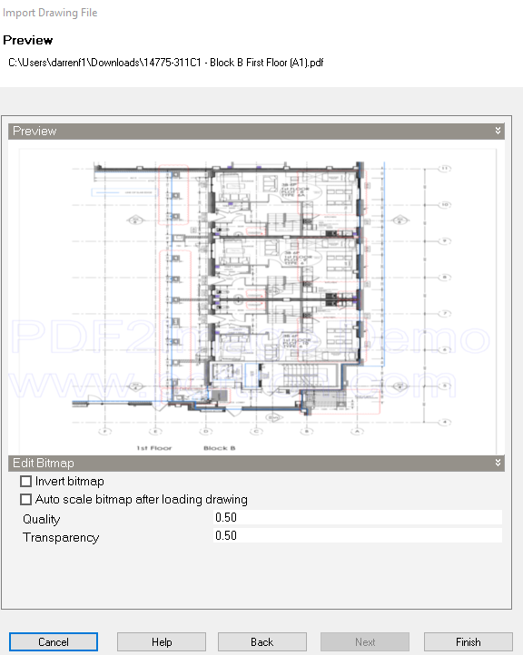
When the file type is one of the bitmap based formats (PDF, BMP, JPG, PNG, GIF, TIFF collectively referred to here as 'bitmap') the next page of the Wizard provides a preview of the drawing and some options.
Invert bitmap
Check this option if you wish the colours in the bitmap to be inverted. For example if the picture is white on a black background then it will generally be best to invert these for use in DesignBuilder.
Auto scale bitmap after loading drawing
If you wish the 'scale bitmap' command to be automatically started when the Import Drawing File Wizard in closed then check this option.
Quality slider
By reducing the number of pixels in the bitmap it is possible to significantly reduce the size of the imported drawing data and hence speed subsequent drawing 'scale' and 'rotate' operations. The default Quality setting of 0.5 gives a good trade-off between image size and readability but if the drawing file is particularly large you may decide to reduce the quality to reduce the memory overhead or, if the drawing is difficult to read you could increase Quality.
Opacity slider
You can control the opacity (transparency) of the drawing data from 0 to 1. A value of 1 means that the imported drawing will be completely opaque and 0 means it will be completely transparent. The default is 0.5.
Bitmap-based files may be used for:
- Existing buildings having paper floor plans that have been scanned into electronic format or,
- Early stage design sketch ideas are available only in bitmap form.
Note: bitmap drawings do not allow end-point snap like DXF but can be an equally effective option for rapid geometry entry in DesignBuilder.
Editing Bitmap data
Once the floor plan data has been imported to the model, it must be selected to allow these operations:
- Move - move the bitmap data.
- Delete - delete the bitmap data.
Also the Set X-axis for imported bitmap and Scale bitmap drawing commands are available from the Edit menu when bitmap data is loaded.
Set X-axis for imported bitmap
Sometimes scanned bitmap files are not exactly aligned to the X-axis and you can use this command to re-orientate the drawing. When the command is started click twice to define the end points of a line in the direction of the X-axis on the imported bitmap data. After the operation the bitmap data is rotated to align with the DesignBuilder X-axis.
Scale bitmap drawing
This command allows you to scale the bitmap data to the correct size using a known dimension in the bitmap image.
When the command is started click twice to define the end points of a reference line on the bitmap data of known length (e.g. a dimension arrow or known length on a building wall). Then either move the cursor to define the new length of the reference line and click again or type in the dimension of the reference line. So a typical sequence might be:
- Start Edit > Scale bitmap drawing command.
- Single click on one end of a large dimension line.
- Single click on the other end of the dimension line.
- Type in the dimension in m or ft (depending on the international units setting) followed by <Enter>.
Important Note: This process will always be necessary for bitmap drawing formats as the scale is not defined at the import stage.
Partitions
You can also use the imported floor plan data to draw internal partitions. To do this go to block level and draw partitions by tracing over using the
floor plan partition data. You should take care to connect partitions to the
external perimeters. A common mistake is to snap partitions to DXF data
lying very close to the external perimeter but not close enough to create
a connection with the external perimeter.
Tip: It is generally best to
switch off DXF snap in the Drawing options panel
when drawing partitions at block level to avoid this problem. Be
sure to switch it back on again when you have finished drawing partitions.