This tutorial will help you get up to speed with running a parametric analysis study in DesignBuilder in a few easy steps.
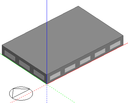
Create a new file located in London Gatwick and add a building to the site with a simple rectangular block having dimensions 30m x 20m as shown below. Use default Model options and template settings. DesignBuilder as supplied will use a Simple HVAC Fan Coil Unit system as the default. For this example you should make sure that you have heating and cooling selected and no natural ventilation (this will be the case for a new model with a FCU HVAC system selected).
Click on the Simulation tab and run a base annual simulation. Because it is a simple model you can select hourly results. Make sure to also choose Monthly results which are required by the Optimisation.
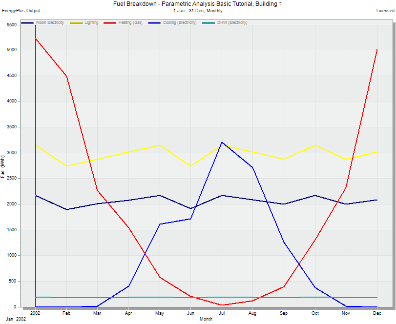
Check the hourly results for the simulation period and make sure that the model is behaving as expected, including temperatures within the building, operations periods etc. If not fix the model and repeat this step until you are happy with the base model hourly results. Monthly results should something like the screenshot below.
Once you have a good understanding of how the base model operates, you are ready to start the parametric analysis stage.
For this simple example we will investigate the effect of changing the Window to Wall Ratio (WWR) and overhang length on building annual heating and cooling loads .
To do that follow these steps.
Step 3.a - Open the Parametric, Optimisation and UA/SA Analysis Settings dialog
Step 3.b - On the Analysis type tab select the 1-Parametric analysis option.
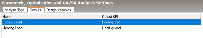
Step 3.c - On the Outputs tab add the Output results for the parametric analysis study - annual heating and cooling load:
Click on the Add Output Info panel link.
On the Analysis Outputs dialog select the Cooling load Output KPI and enter the name as "Cooling Load". Press OK.
Click on the Add Output Info panel link again.
On the Analysis Outputs dialog select the Heating load Output KPI and enter the name as "Heating Load". Press OK.
The Outputs tab should now look like this:
Step 3.d - On to the Design Variables tab.
Window to wall ratio will be already set up by default on a new model and we need to keep this variable for this study. Delete any other variables though. In a default model these will normally be for Cooling and heating setpoint temperatures. Select each of these in the grid and press the Delete variable Info panel link.
You should now have only Window to wall ratio in the Design Variables list.
Click on the Add variable Info panel link.
On the Edit Analysis Variables dialog select the Local shading type Variable type (it can be found under the Glazing/shading category heading). By default this includes 5 levels of overhang length from 0m to 2m. You can keep these default options. Press OK.
The Design Variables tab should now look like this:
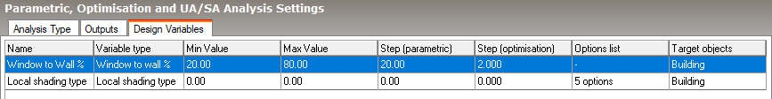
Variations are made at building level for both variables in this case as shown by the Target objects column.
Press OK to confirm changes and close the Parametric, Optimisation and UA/SA Settings dialog.
Click on the Parametric tab of the Simulation screen and click on the Update toolbar icon to open the Calculation options dialog.
Select the Output you would like to see displayed as simulation results are received back from the Simulation Manager.
Once you have completed your review of the options press the Start button in the bottom right of the screen. The process will involve running several simulations (number of options for design variable 1 x number of options for design variable 2).
Simulations are run in parallel using the Simulation Manager.
Once simulations are complete, close the Calculation options dialog.
Choose the Parametric output to display on the Display options panel to the bottom left of the main screen.
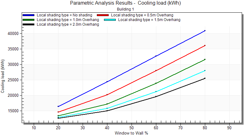
Effect on Cooling load of changing WWR and Overhang length
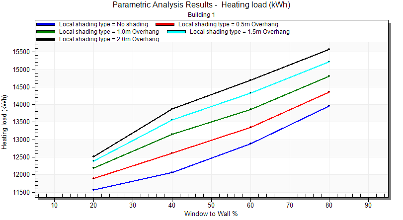
Effect on Heating load of changing WWR and Overhang length
Perhaps not surprisingly the overhang length has a much greater impact on Cooling load than on Heating load.