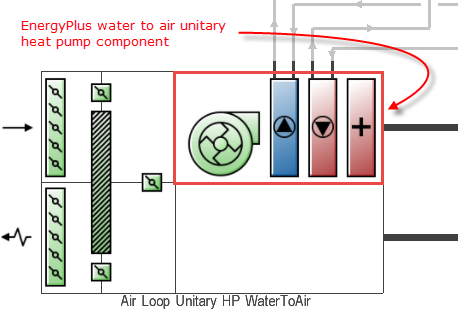
The unitary water-to-air heat pump AHU incorporates an EnergyPlus unitary water-to-air heat pump component, an outdoor air system, optional night cycle operation, an optional heat recovery system, optional pre-heat and pre-cool coils and an optional extract fan. The unitary water-to-air heat pump component itself comprises a supply fan, a water-to-air heat pump cooling coil component, a water-to-air heat pump heating coil component, and an electric, hot water or fuel supplementary heating coil component.
The unitary water-to-air heat pump is similar to the unitary air-to-air heat pump except water is used on the source side, connected to a condenser loop with a heat exchanger (ground heat exchanger or other type) or a plant loop with a heating source such as a boiler and a cooling source such as a chiller or cooling tower.
Note: The Unitary Water to Air Heat Pump AHU can only be added as part of a Unitary Water to Air Heat Pump Air loop .
A detailed description of how Unitary air loops work is provided in the EnergyPlus Engineering Reference.
This is the name that you assign to the AHU which should be unique. If the supplied name is not unique, the software will automatically append a backslash and integer to ensure that there are no duplicate names.
This schedule contains information on the availability of the AHU for operation. A schedule value greater than 0 (usually 1 is used) indicates that the unit can be on during the hour. A value less than or equal to 0 (usually 0 is used) denotes that the unit must be off.
When this unit is unavailable (schedule values of 0) then all equipment contained within this AHU will also be switched off.
This setting defines the design supply air flow rate through the heat pump (in m3/s or ft3/min). This volume flow rate is only used when the cooling and heating coil object type is Parameter Estimation. Although a value greater than 0 is required (input cannot be blank or 0), this input is not used for the Equation Fit coil model. Instead, the supply air flow rate is determined by the input in the corresponding Equation Fit coil objects.
There are two options:
The supply air fan operating mode may vary during the simulation based on time-of-day or with a change of season. Schedule values of 0 indicate that the unitary system supply air fan and the heating or cooling coil cycle on and off together to meet the heating or cooling load (sometimes referred to as an "AUTO" fan). Schedule values other than 0 denote that the supply fan runs continuously while the heating or cooling coil cycles to meet the load.
The default schedule is "Fan operation mode - Continuous" with a constant value of 1, i.e. that the supply fan runs continuously while the heating or cooling coil cycles to meet the load at all times. To obtain the AUTO fan configuration, select the "Fan operation mode - Cycling" schedule which has a constant value of 0.
This is the time delay for the heat pump supply air fan to shut off after the compressor cycles off in seconds. This value can be obtained from the manufacturer or the heat pump catalog. Enter a value of zero when the heat pump’s fan operating mode is continuous. The suggested value is 60 seconds.
While the heat pump may be configured to serve multiple zones, system operation is controlled by a thermostat located in a single “control” zone. Click on the <Select zone> label and then click on the displayed ellipsis button to bring up the zone selector dialog. Select the zone supplied by the AHU where the thermostat controlling the heat pump is located.
Enter the fraction of on-cycle power use to adjust the part load fraction based on the off-cycle power consumption due to crankcase heaters, controls, fans etc. Some suggested value values are provided below (Henderson et al. 1999):
| Heat Pump Condition | Recommended Values |
| Typical | 0.01 |
| Good | 0.01 |
| Poor | 0.03 |
There are two options for dehumidification control:
1‑None - meet sensible load only, no active de-humidification control;
2‑Cool Reheat - cool beyond the dry-bulb temperature set point as required to meet the high humidity setpoint.
Note: If 2‑Cool Reheat is used, a humidistat must be defined in one of the zones supplied by the AHU.
Tip: To provide humidification, a humidifier should be added to the AHU and a setpoint manager added downstream of the AHU with one of the "minimum humidity" control options.
Enter the time constant for the cooling coil’s capacity to reach steady state after startup. Suggested values are shown below (Henderson et al. 1999):
| Heat Pump Condition | Recommended Values |
| Typical | 60 |
| Good | 60 |
| Poor | 60 |
Enter the maximum on-off cycling rate for the compressor, which occurs at 50% run time fraction. Suggested values are shown below (Henderson et al. 1999):
| Heat Pump Condition | Recommended Values |
| Typical | 2.5 |
| Good | 2.5 |
| Poor | 3.0 |
If the heat pump’s DX heating coil output at full load is insufficient to meet the entire heating load, the part load ratio is set equal to 1.0 (compressor and fan are not cycling) and the remaining heating load is passed to the supplemental heating coil. If the outdoor air temperature is below the minimum outdoor air temperature for compressor operation, the compressor is turned off and the entire heating load is passed to the supplemental gas or electric heating coil.
This setting defines the maximum allowed supply air temperature exiting the heat pump supplemental heating coil.
This setting defines the outdoor air dry-bulb temperature above which the heat pump supplemental heating coil is disabled. The temperature for this input field must be less than or equal to 21°C.
This data specifies the way in which water flow through the heat pump coils will be modelled. It is only used when WatertoAirHeatPump:EquationFit coils are used. There are three options:
See Night cycle description for Generic AHU
You can set up Mixed mode controls for the AHU to model optimal interaction between the natural ventilation system (Scheduled or Calculated) and the AHU.
Refer to the main HVAC tab Mixed Mode section for details on the available options.
This numeric value allows the user to determine how close the air side has to be controlled. The lower the value of convergence the better the control of air side conditions and the less the zone temperature fluctuates. However in a poorly designed system, a lower convergence might result in warnings which are caused due to the iteration limit for run time fraction calculation is limited to 20.
This numeric value allows the user to determine how close the air side has to be controlled. The lower the value of convergence the better the control of air side conditions and the less the zone temperature fluctuates. However in a poorly designed system, a lower convergence might result in warnings which are caused due to the iteration limit for run time fraction calculation is limited to 20.