Open topic with navigation
Plenums
HVAC tab in model
data under Mechanical Ventilation
header
A plenum is an air compartment or chamber including uninhabited crawl
spaces, areas above ceilings or below a floor, including air spaces below
raised floors of computer/data processing centers, or attic spaces, to
which one or more ducts are connected and which forms part of either the
supply air, return air or exhaust air system, other than the occupied
space being conditioned.
DesignBuilder Compact HVAC Unitary multizone, Unitary single zone,
VAV and CAV systems can have air supplied and returned via plenums. The system
supply and return plenums in the diagram below serve each of the 3 zones.
There are 4 types of plenum:
- System supply plenum
- a supply air plenum serving all zones
in 3-VAV and 2-Unitary multizone system. If any zone supply plenums have
been specified, the outlet from the system supply plenum will flow through
the zone supply plenum to the zone terminal unit. The system supply plenum
is defined at building level on the HVAC tab under the Plenums header and only one is allowed per simulation.
- System return plenum
- return air plenums serving all zones
in 3-VAV and 2-Unitary multizone systems. If any zone return plenums have
been specified, the return air from the zone will flow through the zone
return plenum and then into the system return plenum. The system return
plenum is defined at building level on the HVAC tab under the Plenums header and only one is allowed per simulation.
- Zone supply plenum
- a supply air plenum serving only this
zone in 3-VAV, 2-Unitary multizone and 1-Unitary single zone systems.
The plenum zone is added to the supply air path after the system splitter
or system-level supply plenum and before the zone terminal unit. The zone
supply plenum is defined at zone level on the HVAC tab under the Plenums header. A zone supply plenum can serve
only one zone.
- Zone return plenum
- return air plenums serving only this
zone in 3-VAV, 2-Unitary multizone and 1-Unitary single zone systems.
The plenum
zone is added to the return air path immediately after the zone and before
the system mixer or system-level return plenum. The zone supply plenum
is defined at zone level on the HVAC tab under the Plenums header. A zone return plenum can serve only one zone.
When specifying a system or zone supply or return plenum you should
enter a unique zone name. The
zone does not need to be in the same block. The zone name you enter is checked just prior to the simulation and not before so you should enter the names with care to avoid mistakes.
Plenum modelling
- Maximum of 1 system
supply plenum allowed per simulation
- Maximum of 1 system
return plenum allowed per simulation
- Each zone
plenum can only serve one zone
- Set the Zone type
of any plenum zones to 4-Plenum. This makes the necessary changes (remaining
requirements and recommendations in bullet list)
- Plenum zones cannot be controlled. Use
the HVAC template <None> to switch
off heating, cooling and mechanical ventilation in all plenum zones.
- Remember to ensure plenum zones have no internal
gains, occupancy, lighting etc.
- We recommend using the 4-Ceiling diffuser interior convection
heat transfer coefficient for plenum zones to model the effect of fast
moving air on surface heat transfer.
- You will probably find it easiest to use the Combined method
for Floor/slab/ceiling definition for models using plenums as each surface
element in the model has just a single construction and you don't have
the confusion of Model data referring to 'raised floors' and 'suspended
ceilings'.
- The floor of a ceiling plenum is the ceiling of
the zone below so you will often define the plenum floor as 'Ceiling tiles'
construction or similar.
If the building you are modelling has more than one plenum zone, each
serving multiple zones you should use zone
plenums. Use virtual partitions to partition the large plenum zones (which
in reality serve multiple zones) into multiple plenum zones, each serving
a single zone. See image below.
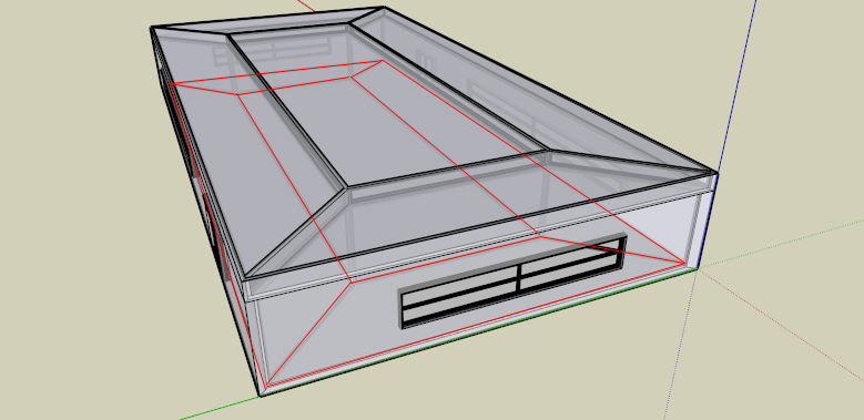
Red lines show the 5 zones of the occupied space. Each zone has its
own return-air ceiling plenum.
This technique is also illustrated in the example file supplied with
DesignBuilder Zone vs System Plenums Example.dsb.
Note 1: when modelling plenums in DesignBuilder there is no need to add holes between the plenum and occupied space to represent supply diffusers or extracts. These are included in the model by EnergyPlus albeit as part of the system network.
Note 2: it is
not possible in DesignBuilder v2 to use the suspended
ceiling/floor (as set on the Constructions tab when using Separate
constructions) as a plenum - the plenum must be a completely separate
zone.