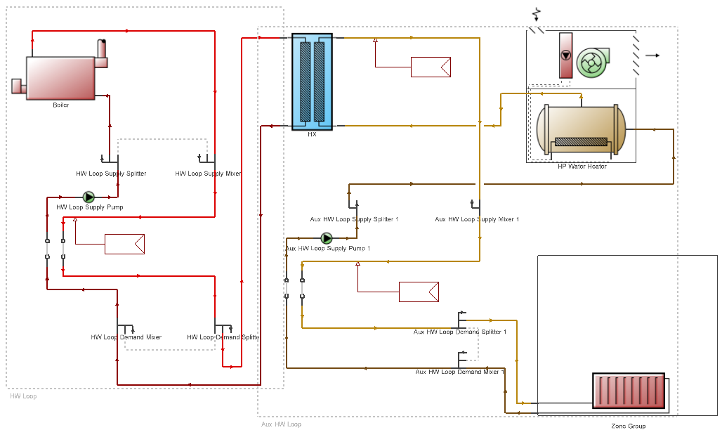
This example explains the main steps involved in setting up an ASHP system. It involves loading an ASHP Detailed HVAC template and modifying some settings to achieve a high-performance low temperature ASHP system with gas-fired boiler supplementary heating.
The steps are as follows.
1. Create a new file located in London Gatwick and add a building to the site with a simple square block having dimensions 10m x 10m. Use default Model options and template settings.
Note: Although this example is based on a simple single zone building model, you could follow the same steps on your own multi-zone model.
2. Set the Detailed HVAC model option.
3. Load the ASHP Air-to-water Heat Pump, Supplementary Boiler, Water Convector Detailed HVAC template to the occupied zone(s).
This provides an air to water heat pump with gas boiler supplementary heater which provides high temperature water.
4. Run the Heating design calculations to obtain the total heating Design Capacity for the building and hence the required heating capacity of the ASHP system.
5. Edit the Air to water heat pump coil
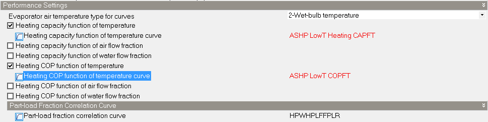
5.1. Change the default high temperature model loaded from the template to use low temperature outlet from the HP. To do this, change the heating capacity and COP function of temperature performance curve settings as follows:
Change Heating capacity function of temperature curve to ASHP LowT COPFT, and
Change Heating COP function of temperature curve to ASHP LowT Heating CAPFT.
The curves section of the dialog should now be similar to the screenshot below.
5.2. Enter the Rated heating capacity of the ASHP. Enter 90% of the design heating load calculated in step 4. The system will rely on the gas boiler to boost overall system capacity to achieve the full capacity.
5.3. To ensure that the rated conditions are consistent with the new curves selected in step 5.1, you should change the Rated evaporator inlet air dry and wet-bulb temperatures to 16°C and 12°C respectively. See below.

6. Next move up a level in the HVAC system hierarchy and edit the Air to water heat pump (Water heater heat pump) and:
7. Edit the Water heater and verify some key inputs:
On the Water heater tab, ensure that the Tank volume is set to Autosize.
On the Sizing tab, check that Design mode is set to 1-Peak draw and the Time for tank recovery is set to 0.6hr.
9. Edit the Boiler and change the capacity of the boiler to provide the remaining 10% of the design heating load.
10. Check that the SPM downstream of the supply side of the HX controls the supply water temperature to 55°C.
11. Change the Pressure rise of the ASHP fan to 100Pa.
12. Finally, run a simulation of the model over the winter to ensure that the overall system is able to meet the heating loads even on the coldest days without excessive use of the supplementary gas-fired boiler. You should see results similar to those shown below.
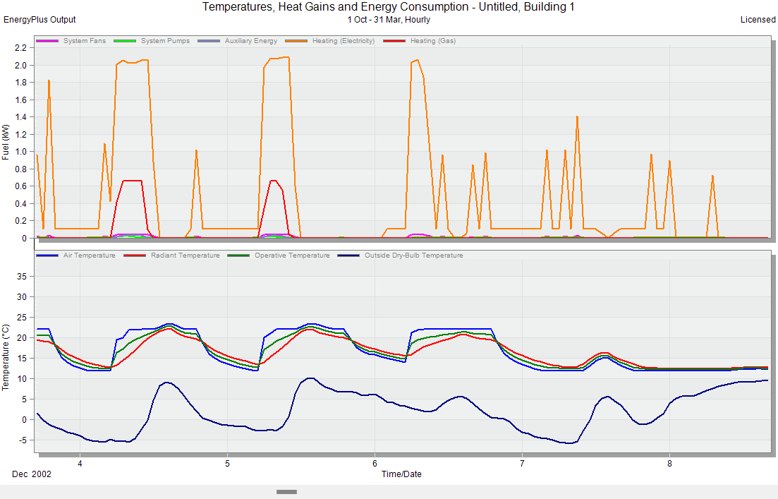
Note how the gas boiler only needs to fire on the coldest periods.