Openings tab in model data under External Glazing and Internal Glazing headers
You can use settings such as Window to wall % (WWR) and Window height, Window spacing and Sill height to easily change the amount of glazing and its layout on the walls. The way this data is used for each façade type is described below.
There are a number of standard façade types:
Often referred to as the Window to Wall Ratio (WWR) this setting is a fundamental parameter in DesignBuilder used to control the proportion of glazing on building façades. It can be used to change the amount of glazing for all openings at or below the current level in the building hierarchy. For example changing the WWR at building level changes the size of all windows in the model not overridden by other settings lower in the hierarchy.
When using the 2-Outer volume Zone geometry and surface areas option (typically one of the "External measurements " convention templates) it is important to understand that the reference surface area used when calculating the window area from the % value supplied is based on the Window to wall ratio method which is accessed from the Constructions tab under the Geometry Areas and Volumesheader.
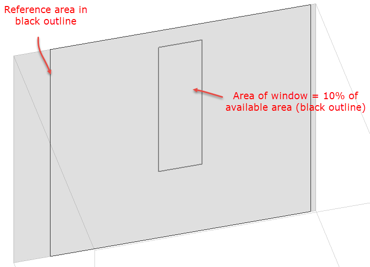
The image below illustrates a wall in a model using the "External measurements" geometry convention template where a window has been created using the 3-Preferred height façade option with a 10% glazing ratio. You can see the black outline showing the available area where the window could possibly be sited. Areas outside this outline to the left and right are taken up by corners with adjacent walls. The % glazing calculation uses the black outline area as the reference area. In an extreme case where 100% glazing is specified the whole of this area would be filled with window, but of course the sides of the surface where there is a corner with an adjacent surface cannot contain a window and so do not take part in the calculation - even though they will form part of the surface used in the simulation.
Tip: If you need to ensure that the % window areas used in the simulation exactly match the % you define here then you should consider using the Simple Geometry convention template which ensures that 100% of each surface is available for containing windows by using zero surface thickness for all surfaces.
Note: If any custom windows are drawn on a surface, the automatic (aka default) façade mechanism described on this page using Window to Wall % (WWR), window width, height, spacing etc is not applied any more. The façade mechanism can be reinstated using the Clear data to default option. For more information see expanding text below.
The behaviour of the WWR % setting changes significantly when custom windows are introduced. This section explains how WWR % operates in DesignBuilder and its interaction with custom windows, especially in the context of using parametric tools.
How WWR % Functions in DesignBuilder
Default Façade Mechanism
WWR % automatically sizes and places windows on building façades based on the specified ratio. This setting can be applied at building, block, zone, and surface levels.
Parametric Tools:
WWR % is commonly used as a variable in parametric studies to evaluate the impact of different glazing ratios on building performance.
Impact of Using Custom Windows
Override of Default Mechanism:
When you manually draw or size windows (custom windows) on a surface, the automatic façade mechanism—including WWR %, window width, height, and spacing—is disabled for that surface.
WWR % Not Applicable:
For surfaces with custom windows, changes to the WWR % setting will not affect those windows. Only the manually defined windows are considered in calculations.
Restoring WWR % Control:
To re-enable WWR % control, use the “Clear data to default” option. This removes custom windows and reinstates the automatic façade mechanism.
Practical Implications for Parametric Calculations
If your parametric study relies on varying WWR %:
- WWR % will only affect surfaces without custom windows.
- Custom windows remain fixed in size and position, regardless of WWR % changes during parametric runs.
To ensure WWR % is applied throughout your model:
- Avoid drawing custom windows, or clear them before running your parametric analysis.
- Use the default façade settings to allow WWR % to control window area and placement.
The width of the windows including any frame (in m or ft).
The height of the windows including any frame (in m or ft).
The spacing between the each window on the façade (in m or ft). The window spacing is the centre to centre spacing between windows, not the gap between windows.
This is the height of the base of the window from the base of the block (in m or ft).
Note 1: You can control the configuration of the building façades in greater detail by drawing individual "custom" windows at the surface level or by copying previously drawn windows at building level. In either of these cases glazing, vent and door façade layout model data is ignored.
Note 2: Flat roofs do not have default glazing set up using Roof glazing layout model data. To create openings on a flat roof you should go to the surface level and add them there.
Note 3: When the surface is non-rectangular, even with the 2 façade type options that prioritise Window to wall % (3-Preferred height and 1-Continuous horizontal), the Window to wall % will not be perfectly maintained. For these surfaces, DesignBuilder calculates a rectangle that can accept the windows and starts from one end of the rectangle adding windows using the Window spacing data until no more fit into the rectangle. This results in an approximately correct looking façade but only prioritises Window to wall % in the rectangle, not accounting for the areas outside the bounding rectangle. For relatively large values of Window spacing on non-rectangular surfaces, no glazing may be generated. For example you may find that gable window surfaces have no default windows generated and it is often easiest to draw a window in this case.
The outside reveal depth gives the extent to which the glazing is offset into the wall. As shown in the diagram on the Frame and Dividers page it is the distance from the exterior surface of the wall to the glazing outer surface (in m or ft).
Note: The outside reveal depth is used in EnergyPlus, Visualisations and Daylighting calculations and (unlike Inside reveal depth) is available regardless of whether the frame and dividers are included.
Note: EnergyPlus models outside reveals through the co-ordinates of the window, which are offset into the zone so the window and the base surface don't lie on the same plane. DesignBuilder provides window co-ordinates to EnergyPlus in this way and there is no specific data item in the IDF data to define it.
See also Inside reveal depth.
The FenestrationSurface:Detailed window data written to the EnergyPlus IDF input file will usually have a smaller area compared with the gross window area defined in DesignBuilder. EnergyPlus window sizes and positions are defined for the glazing area and the frame is extended from the window position to the parent wall/roof surface. DesignBuilder therefore accounts for the frame which is included in the window area defined in DesignBuilder but excluded from the EnergyPlus IDF window area. In cases where the frame option is switched off in DesignBuilder the frame area in the IDF data will exactly match the area set in DesignBuilder.
See also: