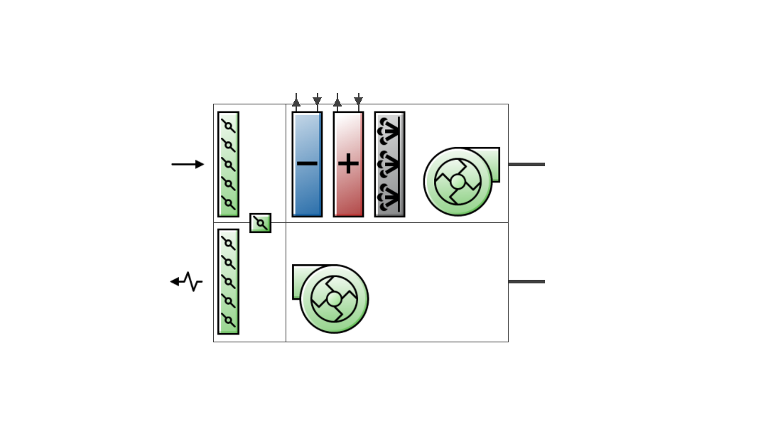
The basic generic AHU incorporates an outdoor air system and a supply fan. There are also options for night cycle operation, a heat recovery system, an economiser, pre-heat and pre-cool coils and an extract fan. Additional components such as heating coils, cooling coils and humidifiers may also be added to generic AHUs.
 See the Generic Air Loops Tutorial
This is the name that you assign to the AHU which should be unique. If the supplied name is not unique, the software will automatically append a backslash and integer to ensure that there are no duplicate names.
This setting is used to indicate a Constant Air Volume (CAV) or Variable Air Volume (VAV) system. It can take one of two values:
Note 1: Once an air loop has been connected to a zone ADU, the Fan type setting is fixed (greyed out) preventing an invalid connection and remains greyed out until the air loop is disconnected from all ADUs. So to change an air loop from VAV to CAV or vice-versa using this control you must first disconnect the demand side of the air loop from all zone ADUs. You can do this by deleting connecting branches.
Note 2: Once the AHU fan type has been set, the air loop containing the AHU can only be connected to valid zone air distribution units (ADU), i.e. CAV air loops can only be connected to CAV ADUs and similarly VAV systems can only be connected to VAV ADUs.
This is the air loop primary air design volumetric flow rate (in m3/s or ft3/min). This setting is auto-sizeable.
This schedule contains information on the availability of the AHU for operation. A schedule value greater than 0 (usually 1 is used) indicates that the unit can be on during the hour. A value less than or equal to 0 (usually 0 is used) denotes that the unit must be off.
When this unit is unavailable (schedule values of 0) then all equipment contained within this AHU will also be switched off.
This setting may be used to enable cycling of an air system when one or more zones become too hot or too cold. A common requirement for this mechanism is where the AHU is turned off at night. However if the building gets too cold there might be condensation on the walls and other damage. Thus the control system is usually programmed to turn the system on either if a specified control thermostat or any thermostat shows a zone temperature of less than a night time set point. Similarly, there might be a concern about a building getting too hot. Again the control system is programmed to turn the AHU back on if one or any zone temperature exceeds a night time cooling set point.
This mechanism offers considerable flexibility in determining how the night time on/off decision will be made. The temperature in one specific zone may be used or the temperatures in all the zones connected to the AHU may be sampled. You can specify a temperature tolerance and a run time for the system once it switches on. There is also an applicability schedule for scheduling when this mechanism may be applied.
This schedule determines whether or not for a given time period this mechanism is to be applied. Schedule values greater than zero (usually 1 is used) indicate the night cycle mechanism is to be applied, whereas schedule values less than or equal to zero (usually 0 is used) denote that it is not used for this time period.
The possible inputs are:
Important Note: Plant loops and any required zone units must be available during the night cycle by amending the availability schedules appropriately. The night cycle availability manager only automatically overrides the air loop fan schedule.
This is the amount (in °C or °F) by which the zone temperature must exceed the cooling set point or fall below the heating set point in order for the night cycle mechanism to signal that the system should turn on.
The time in seconds for which the system will run after it has cycled on. The default is 3600 seconds (1 hour).
For the Control Type option 3‑Cycle on control zone select the control zone.
An extract fan is included within all AHUs by default. This setting may be used to remove the extract fan from the AHU.
Note: If the AHU is connected to a zone that incorporates a Variable Air Volume with Reheat and Variable Speed Fan ADU, the AHU extract fan should be omitted otherwise EnergyPlus will raise an error and the simulation will be aborted.
You can set up Mixed mode controls for the AHU to model optimal interaction between the natural ventilation system (Scheduled or Calculated) and the AHU.
Refer to the main HVAC tab Mixed Mode section for details on the options available.
Note: If mixed mode is activated here on the AHU dialog, then any mixed mode settings for connected zones on the HVAC tab will be overriden by these mixed mode settings.
The outdoor air system incorporates an air mixer, an optional pre-cool coil, an optional pre-heat coil, an optional heat recovery device and an outdoor air controller. The purpose of the outdoor air controller is to provide outdoor air for ventilation and also provide free cooling (through additional outdoor air and/or bypassing an air-to-air heat exchanger) whenever possible. The outdoor air controller includes a number of user-selectable limit controls. If any of the selected limits are exceeded, the outdoor airflow rate is set to the minimum.
If all the limits are satisfied, the outdoor air controller does the following for continuous air flow systems: if the outdoor air temperature is greater than or equal to the mixed air temperature setpoint, the outdoor air flow rate is set to the maximum; if the outdoor air temperature is less than the mixed air temperature setpoint, the outdoor air controller will modulate the outdoor air flow so that the mixed air temperature will match the mixed air setpoint temperature.
A time-of-day schedule may also be used to simulate an increase in outdoor air flow rate for “push-button” type economiser applications. When the schedule permits (i.e., schedule values are greater than 0), the outdoor air flow rate is increased to the user-specified maximum outdoor air flow rate.
The outdoor air controller can also account for changes in the outdoor air flow rate during times when indoor humidity levels are high. A zone humidistat must be used with this control option. During high indoor humidity, the outdoor air flow rate is modified in response to a high indoor humidity condition. If high humidity control is based on the outdoor air humidity ratio and the outdoor humidity ratio is greater than the indoor humidity ratio, high humidity control is terminated. When the economiser is used in conjunction with the high humidity control option, high humidity control has priority and controls the change in air flow rates. If the AHU Night Cycle option is switched on, it has priority over high humidity control and will use the controller’s maximum outdoor air flow rate when the Night Cycle mechanism cycles the fan on.
Optional pre-cool coil, pre-heat coil and heat recovery may be specified upstream of the mixer. When this is the case, any modulation will be determined by the conditions at the inlet node of the mixer rather than the outdoor air. This means that the controller will account for the heat recovery device or pre-heating/pre-cooling coils that may modify the condition of outdoor air before it reaches the mixer. If all the limits are satisfied, the outdoor air controller does the following for cycling fan systems: the outdoor air flow rate is set to the maximum when the fan cycles on. If the limits are not satisfied, the outdoor air flow rate is at the minimum when the fan cycles on.
This is a read-only label that is automatically generated by the software and which incorporates the name of the air loop in which the AHU is located.
If this option is checked, the AHU will re-circulate a proportion of the air delivered by the AHU, otherwise the system will operate as a full fresh air system.
If you need to model a full fresh air system with no recirculation but need some of the functionality under the Recirculation check box, such as an economiser, you should check the Recirculation checkbox and make the following settings:
The screenshot below shows how the data should look when you are finished.
These settings ensure that the fraction of fresh air is 1 at all times and that there is no recirculation.
This is the minimum outdoor air flow rate for the system (in m3/s or f3/min).
This is the maximum outdoor air flow rate for the system (in m3/s or ft3/min).
Choices for this field are:
An economiser can be included to provide free cooling by increasing the flow of outdoor air into the AHU mixing box when conditions are favourable. The types of economiser available are:
In addition to all economiser control types listed above, each control type checks for user-entered values for the upper limit of dry-bulb temperature, enthalpy limit, humidity ratio limit and dew-point limit. The outdoor air flow rate is set to minimum if any of these entered limits are exceeded.
Note: The economiser acts to control the temperature of the mixed air stream regardless of the type of economiser.
The way that the economiser air flow rate is controlled is illustrated in the diagram below.
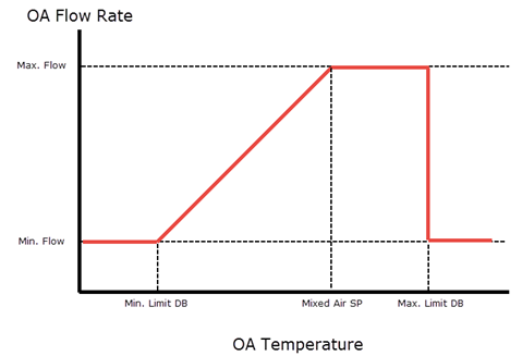
Economiser optimiser control action
When the economiser control type is set to 4‑Fixed Enthalpy, the Max. Limit DB would be replaced by the enthalpy value entered for the Economiser maximum limit enthalpy setting, i.e. instead of switching the OA flow to minimum when the OA temperature reaches the specified maximum, it would switch to minimum when the OA enthalpy reaches the specified maximum. The optimiser is still working though to maintain the setpoint temperature for the mixed air stream.
Note: A cooling or scheduled temperature setpoint manager must be included on the supply side of the air loop when an economiser is selected. This will typically be downstream of the AHU.
There are two choices:
This option is only available for Unitary Heat Cool or Unitary Heat Pump AHUs. Choices for this setting are:
This is an optional outdoor air temperature low limit (in °C or °F) for economiser operation. If the outdoor air temperature is below this limit, the outdoor airflow rate will be set to the minimum. This limit applies to the conditions at the Actuator Node regardless of whether or not there are any other components in the outdoor air path upstream of the mixer.
This is an optional outdoor air temperature high limit (in °C or °F) for economiser operation. If the outdoor air temperature is above this limit, the outdoor airflow rate will be set to the minimum. This limit applies to the conditions at the Actuator Node regardless of whether or not there are any other components in the outdoor air path upstream of the mixer.
This is an optional outdoor air enthalpy limit (in J/kg or Btu/lb) for economiser operation. If the outdoor air enthalpy is above this value, the outdoor airflow rate will be set to the minimum. This field is required if the Economiser type is set to 4‑Fixed enthalpy. This limit applies to the conditions at the Actuator Node regardless of whether or not there are any other components in the outdoor air path upstream of the mixer.
This is an optional outdoor air dew-point limit (in °C or °F) for economiser operation. If the outdoor air dew-point temperature is above this value, the outdoor airflow rate will be set to the minimum. This limit applies to the conditions at the Actuator Node regardless of whether or not there are any other components in the outdoor air path upstream of the mixer.
This is an optional Quadratic or Cubic curve which provides the maximum outdoor air humidity ratio (function of outdoor air dry-bulb temperature) for economiser operation. If the outdoor air humidity ratio is greater than the curve’s maximum humidity ratio (evaluated at the outdoor air dry-bulb temperature), the outdoor air flow rate will be set to the minimum. This limit applies to the conditions at the Actuator node regardless of whether or not there are any other components in the outdoor air path upstream of the mixer.
This is an optional schedule which controls the outdoor air flow rate based on a time-of-day economiser. Schedule values equal to 0 disable this feature. A schedule value of greater than 0 causes the outdoor air flow rate to increase to the maximum. When an economiser is used in conjunction with the high humidity control option, high humidity control has priority.
This setting establishes whether or not the outdoor air flow rate is modified in response to high indoor relative humidity. If 2‑Yes is selected, the outdoor air flow rate may be modified when the indoor relative humidity is above the humidistat setpoint. If 1‑No is selected, this option is disabled and the following three settings are not displayed.
This is the zone name where the humidistat is located. This setting is only required when the High Humidity Control is set to 2‑Yes.
This is the ratio of the modified outdoor air flow rate to the maximum outdoor air flow rate. When the high humidity control algorithm determines that the outdoor air flow rate will be changed (i.e. increased or decreased), the operating outdoor air flow rate is equal to the maximum outdoor air flow rate multiplied by this ratio. The minimum value for this setting is 0. This setting is only required when the High humidity control is set to 2‑Yes. When an economiser is used in conjunction with the high humidity control option, high humidity control has priority.
This setting determines if high humidity control is activated based on high indoor relative humidity alone or is activated only when the indoor relative humidity is above the humidistat setpoint and the indoor humidity ratio is greater than the outdoor humidity ratio. Valid choices are 1‑Yes and 2‑No. If 2‑No is selected, high humidity control is active any time the zone humidistat senses a moisture load. If 1‑Yes is selected, the model also verifies that the outdoor humidity ratio is less than the humidistat’s zone air humidity ratio. This setting is only required when the High Humidity Control is set to 2‑Yes.
Note: While conditions may be favourable for economizer operation, it does not guarantee that the air-side economizer has increased outdoor air flow above the minimum level since the actual outdoor air flow rate is also governed by other controls (e.g., mixed air set point temperature, time of day economizer control, maximum humidity setpoint, etc).
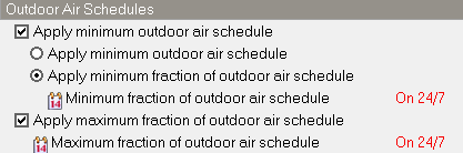
If the minimum outdoor air flow rate is to be scheduled then check this option to reveal 2 further sub-options which are controlled using radio buttons:
The screenshot below shows how to change the AHU Outdoor Air Schedule settings to obtain outdoor air varying between the maximum value defined on the HVAC tab and zero based on occupancy schedule "Office_OpenOff_Occ", in the same way as it does with Simple HVAC.

When outdoor air delivery to zones is to be controlled accurately as described above it is necessary to make 3 further settings:
It is important to understand that even with the above settings you won't generally obtain exact specified outdoor air flow rates to individual zones, however the total fresh air supply rate provided through the AHU should be correctly calculated as the sum of the minimum fresh requirements of all zones served by the AHU. This is because the total outdoor air requirement for each zone on the air handler is summed and used to set the minimum total outdoor air flow rate for the air handler. The outdoor air controller sets an outdoor air flow rate for the air handler at each time step during the simulation. After that, each zone receives a pro-rated share of the total outdoor air flow proportioned by the current supply flow rate to each zone, but the exact supply flow rate to each zone will be calculated based on cooling or heating demand not fresh air requirements and there is no further zone-by-zone allocation of outdoor air quantities - which is what happens in a real system.
When the Apply minimum outdoor air schedule checkbox is checked you can select this schedule which uses decimal values (0.0 – 1.0). These values are multiplied by the minimum outdoor air flow rate. This schedule is useful for reducing the outdoor air flow rate to zero during unoccupied or start up hours. If this schedule option is not used, the minimum outdoor air flow rate either remains constant during the simulation period (Minimum limit type = 2‑Fixed minimum) or varies in proportion to the supply air flow rate (Minimum limit type = 1‑Proportional minimum).
When the Apply minimum fraction of outdoor air schedule checkbox is checked you can select this schedule which uses decimal values (0.0 – 1.0). These values are multiplied by the design supply air flow rate. This is an alternate method for specifying the minimum outdoor air amount. The other method is the Minimum outdoor air schedule described above.
Note: If both the Minimum outdoor air schedule and the Minimum fraction of outdoor air schedule are both selected then for each timestep of the simulation, the higher of the two minimum limits is calculated and applied. Both of these settings act by overriding the Outdoor air flow rate.
Check this option to limit the maximum outdoor air flow rate.
When the above Apply maximum fraction of outdoor air schedule option is selected you can also select the corresponding schedule which has fractional values in the range 0.0-1.0. This schedule effectively enables you to limit the maximum amount of outdoor air into the system.
Ventilation standards provide guidance on appropriate levels of outdoor ventilation air required for acceptable indoor air quality. For example the Ventilation Rate Procedure (VRP) of ASHRAE Standard 62.1-2007/2010 requires outdoor ventilation rates to be determined based on the floor area of each occupied zone plus the number of people in each zone and considers the zone air distribution effectiveness and system ventilation efficiency. The outdoor air ventilation rate can be reset dynamically as operating conditions change (e.g. variations in occupancy).
The VRP option can be used for calculating these outdoor air ventilation requirements and resetting them based on varying occupancy levels and zone diversification. This is particularly useful for large air distribution systems that serve a number of different zone types with varying occupancy levels.
DCV control can also be used to model the Indoor Air Quality Procedure (IAQP) as defined in Standard 62.1
Check this option to include DCV controls for this AHU.
Select the method to be used to calculate the system minimum outdoor air flow. 5 choices are available:
Note: If either 1-Zone sum or 2-Ventilation Rate Procedure (VRP) options are selected here then the CO2 and contaminant option does not need to be selected on the HVAC zone dialog.
Note: If either 3-Indoor Air Quality Procedure (IAQP) or 6-Indoor Air Quality Procedure (IAQP) generic contaminant are selected then the CO2 and contaminant option must be selected for at least one HVAC zone connected to the AHU.
Note: When one of the proportional control methods is selected (4-Proportional control based on occupancy schedule or 5-Proportional control based on design occupancy) then selection of the CO2 and contaminant HVAC zone options is optional. If zone minimum CO2 concentration settings for proportional control are to be specified then you should check it, otherwise leave it unchecked.
Note: When using DCV you should ensure that the Minimum outdoor air flow rate is set to zero and not to Autosize. This is the opposite of the requirement when scheduling outdoor air flow without using DCV.
A summary guide on the steps required to model DCV is provided in the Modelling advice section.
For more details on how DCV is simulated in EnergyPlus see the DCV page in the EnergyPlus Engineering Reference Guide.
For VAV systems, when a zone requires outdoor air higher than the user specified Zone Maximum Outdoor Air Fraction, the zone supply air flow will be increased (if damper not fully open yet) to cap the outdoor air fraction at the maximum value. This allows the system level outdoor air flow to be reduced while the total supply air flow increases to meet zone outdoor air requirement. Valid values are from 0 to 1.0. Default is 1.0 which indicates zones can have 100% outdoor air maintaining backward compatibility. This inputs work for single and dual duct VAV systems.
Select the schedule which defines when DCV should operate. If the schedule’s value is 0.0, then mechanical ventilation is not available and flow will not be requested. If the schedule’s value is > 0.0 (usually 1 is used), mechanical ventilation is available.
Tip: This schedule can be useful for purging the building of contaminants prior to occupancy (i.e., ventilation rate per unit floor area will be provided even if the occupancy is zero).
The minimum quantity of outdoor air delivered via the mixed air box will be the greater of:
The actual outdoor air flow rate may be higher than the minimum if free cooling is available. Regardless, the outdoor air flow rate will not exceed the Maximum outdoor air flow rate
If this option is checked, the AHU will incorporate a sensible and latent air-to-air heat recovery device capable of both heating and cooling the supply air stream using waste energy from the exhaust side.
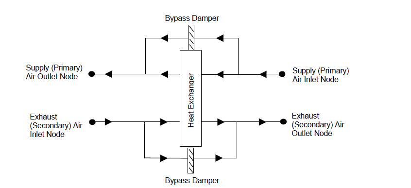
Heat exchanger performance can be specified to transfer sensible energy, latent energy or both between the supply and exhaust air streams. The input requires no geometric data. Performance is defined by specifying sensible and/or latent effectiveness at 75% and 100% of the nominal (rated) supply air flow rate at two operating conditions as shown in the following table:
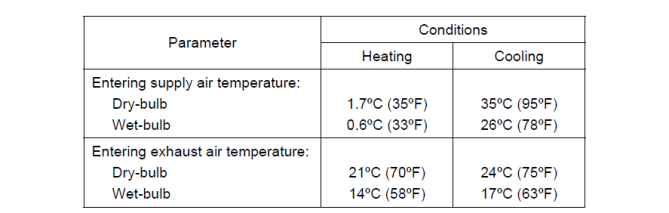
Operating Conditions for Defining Heat Exchanger Performance.
Note: Conditions consistent with the Air-Conditioning and Refrigeration Institute’s (ARI) Standard 1060-2001
Heat exchange between the supply and exhaust air streams occurs whenever the unit is scheduled to be available (Availability schedule) and supply/exhaust air flow is present. Heat recovery can be used in conjunction with a conventional air-side economiser (select 1‑Modulate flow for the Economiser control action type), whereby heat exchange is suspended whenever the air-side economiser (or high humidity control) is active (i.e. air flow is fully by-passed around a fixed-plate heat exchanger or the rotation of a rotary heat exchanger is stopped). It is also possible to suspend heat exchange for the purpose of providing free cooling operation in the absence of a conventional air-side economizer (i.e. specify 2‑Minimum flow with bypass for the Economiser control action type). During winter weather, humid exhaust air entering the heat exchanger can form frost on the cold heat exchanger surfaces, which can reduce air flow and the amount of energy recovery. Several methods are used to control or eliminate frost formation, and the following types can be modelled for this heat exchanger object: supply air pre-heat, minimum exhaust air temperature, exhaust air recirculation and exhaust only. For preheat frost control, the Pre-heat Coil option must be checked under the Pre-Treatment header. The other frost control types may be selected using the Frost control type drop-list.
Air-to-air heat exchangers are sometimes controlled to maintain a fixed supply air outlet temperature to avoid overheating. DesignBuilder provides an option to model this control in EnergyPlus by automatically including a Setpoint manager to establish a temperature set point at the supply air outlet node of the heat exchanger. Wheel speed modulation or plate supply air bypass is used to control the supply air exiting conditions to this set point. The set point for supply air temperature control should be set at the minimum economizer temperature set point if an air-side economizer is also being used by the air system. If frost control and supply air outlet temperature control are used, frost control takes precedence over supply air temperature control (e.g. Control defrost time fraction is determined as if wheel speed modulation or plate supply air bypass is not used).
The 4 methods listed below are can be used to help control heat recovery systems.
Note: Although an economiser is included in some methods, its main purpose is to provide control of the heat recovery and not free cooling. If effective free cooling is required then you should consider using the 1‑Modulate flow economiser option.
Control method 1: Scheduled heat recovery heating setpoint: When using heat recovery with Supply air outlet temperature control and without an economiser the heat recovery unit heats the outside air up to the heat recovery setpoint and no higher while the outside air temperature is below the setpoint. The heat recovery unit is bypassed when the temperature setpoint is satisfied. When the outside air temperature rises above the heat recovery setpoint the heat exchanger is not bypassed running at full capacity and heating the air as much as possible. This can lead to high supply temperatures when it is warm outside. Overall this control method works well for lower outdoor air temperatures but not so well in summer.
Control method 2: Fixed heating setpoint with economiser: To avoid the overheating caused by Control method 1 an economiser can be introduced with the following settings:
- Economiser control type = 2-Fixed dry bulb
- Outdoor dry-bulb temperature low limit control = On
- Economiser maximum limit dry-bulb temperature = Fixed heat recovery setpoint temperature, e.g. 12°C.
- Economiser control action type = 2-Minimum flow with bypass
- Heat recovery bypass control type = 1-Bypass when within economiser limits
- Heat recovery Supply air outlet temperature control = 2-Yes
This works well reducing overheating relative to method 1, but it only provides a single fixed heat recovery setpoint temperature for the year which makes it difficult to achieve optimal control.
Control method 3: Heat recovery outdoor air temperature setpoint: Another approach to controlling heat recovery is to use the heat exchanger only when the outside air temperature is below a setpoint, and for warmer outside conditions bypass the heat recovery unit. The following settings achieve this:
- Economiser control type = 2-Fixed dry bulb
- Outdoor dry-bulb temperature low limit control = On
- Economiser maximum limit dry-bulb temperature = 50 (high value to avoid heat recovery operation during warm conditions)
- Economiser control action type = 2-Minimum flow with bypass
- Heat recovery bypass control type = 1-Bypass when within economiser limits
- Heat recovery Supply air outlet temperature control = 1-No
Control method 4: Use EMS. An EMS program can be written to control the heat recovery unit in a more optimal way. An example script is shown below which is based on Control method 1 but overrides the HR setpoint temperature and/or availability schedules to simulate a control system which provides the full benefit of HR in winter and bypasses the heat exchanger in warmer conditions when HR is not required:
!- EMS Program: HR Optimal Control Strategy 2 - Stepped HR Setpoint + Zone Temp Sensing
EnergyManagementSystem:Sensor,
Toa,
Environment,
Site Outdoor Air Drybulb Temperature;
EnergyManagementSystem:Sensor,
TempBlock1Zone1, ! Name
Block1:Zone1 , ! Zone name
Zone Mean Air Temperature ; ! Output:Variable or Output:Meter Name
EnergyManagementSystem:Actuator,
OverrideHRAvailability, !- Name
HR Availability Schedule, !- Actuated Component Unique Name
Schedule:Compact, !- Actuated Component Type
Schedule Value; !- Actuated Component Control Type
EnergyManagementSystem:Actuator,
OverrideHRSetpointTemp, !- Name
HR Setpoint Schedule, !- Actuated Component Unique Name
Schedule:Compact, !- Actuated Component Type
Schedule Value; !- Actuated Component Control Type
EnergyManagementSystem:ProgramCallingManager,
Optimise HR , !- Name
BeginTimestepBeforePredictor, !- EnergyPlus Model Calling Point
CalcHRSetpoint; !- Program Name
EnergyManagementSystem:Program,
CalcHRSetpoint,
! Stepped control of HR setpoint temp depending on outside air temp
IF Toa < 8,
Set OverrideHRSetpointTemp = 20.0,
ELSEIF Toa < 12,
Set OverrideHRSetpointTemp = 16.0,
ELSE,
Set OverrideHRSetpointTemp = 12.0,
ENDIF,
IF Toa > OverrideHRSetpointTemp,
Set OverrideHRAvailability = 0, ! Avoid E+ HR control quirk
ELSEIF TempBlock1Zone1 > 23,
Set OverrideHRAvailability = 0, ! avoid HR when room temp more than 23
ELSE,
Set OverrideHRAvailability = 1, ! Otherwise HR is available
ENDIF;
Other possibilities include checking for zone heating and/or cooling loads to help ensure optimal HR setpoints.
The nominal primary side (supply) air flow rate (in m3/s or ft3/min). The actual supply and exhaust air flow rates must be between 50% and 130% of this value or a warning will be issued.
This is the electric consumption rate of the device (W). Electric power is considered constant whenever the unit operates. This numeric input can be used to model electric power consumption by controls (transformers, relays, etc.) and/or a motor for a rotary heat exchanger. None of this electric power contributes thermal load to the supply or exhaust air streams. The default value for this field is 0.
This selection determines whether specialized control is to be used to optimise the use of heat recovery. Options are:
This data determines if the heat exchanger’s supply air outlet is controlled to a temperature set point. The choices for this input field are 1-Yes or 2-No, with the default being 2-No. When supply air outlet temperature control is used, the wheel rotational speed modulates or supply air is bypassed around the plate heat exchanger to maintain the desired setpoint temperature.
When 1-Yes is selected you can enter the setpoint temperature to be used in the next text box below. In this case DesignBuilder automatically adds a scheduled Setpoint manager at the heat recovery supply air outlet node using the entered set point temperature. When an air-side economizer is also being modelled for this air system, the set point for the supply air outlet temperature control is forced to be equal to the Economizer minimum limit dry-bulb temperature.
When 1-Yes is selected for Supply air outlet temperature control you can enter the setpoint temperature to be used for controlling the heat recovery unit as described above.
This setting is used to define the type of heat exchanger being modelled. The options are:
Plate heat exchangers can be either sensible only when plates are made of a non-porous material such as aluminium, or they can also exchange latent heat when the plates are made of a porous material.
The heat exchanger type affects the modelling of frost control options and supply air outlet temperature control. For rotary heat exchangers, rotational speed is varied to control frost formation or the supply air outlet temperature. For plate exchangers, air bypass around the heat exchanger is used to obtain the desired effect.
This input denotes whether the heat exchanger unit is locked out (bypassed for plate type heat exchangers or the rotation is suspended for rotary type heat exchangers) when the air-side economiser is operating. Both the economiser and High Humidity Control activate the heat exchanger lockout as specified by this input. The input choices are 1‑Yes (meaning locked out) or 2‑No.
The sensible heat exchange effectiveness at the heating condition defined in the Table above with both the supply and exhaust air volume flow rates equal to 100% of the nominal supply air flow rate specified in the previous input field. The default value for this field is 0.
The latent heat exchange effectiveness at the heating condition defined in the Operating Conditions for Defining Heat Exchanger Performance table with both the supply and exhaust air volume flow rates equal to 100% of the nominal supply air flow rate. Specify this value as 0.0 if the heat exchanger does not transfer latent energy. The default value for this field is 0.
The sensible heat exchange effectiveness at the heating condition defined in the Operating Conditions for Defining Heat Exchanger Performance table with both the supply and exhaust air volume flow rates equal to 75% of the nominal supply air flow rate. The default value for this field is 0.
The latent heat exchange effectiveness at the heating condition defined in the Operating Conditions for Defining Heat Exchanger Performance table with both the supply and exhaust air volume flow rates equal to 75% of the nominal supply air flow rate. Specify this value as 0.0 if the heat exchanger does not transfer latent energy. The default value for this field is 0.
The sensible heat exchange effectiveness at the cooling condition defined in the Operating Conditions for Defining Heat Exchanger Performance table with both the supply and exhaust air volume flow rates equal to 100% of the nominal supply air flow rate. The default value for this setting is 0.
The latent heat exchange effectiveness at the cooling condition defined in the Operating Conditions for Defining Heat Exchanger Performance table with both the supply and exhaust air volume flow rates equal to 100% of the nominal supply air flow rate. Specify this value as 0.0 if the heat exchanger does not transfer latent energy. The default value for this setting is 0.
The sensible heat exchange effectiveness at the cooling condition defined in the Operating Conditions for Defining Heat Exchanger Performance table with both the supply and exhaust air volume flow rates equal to 75% of the nominal supply air flow rate. The default value for this setting is 0.
The latent heat exchange effectiveness at the cooling condition defined in the Operating Conditions for Defining Heat Exchanger Performance table with both the supply and exhaust air volume flow rates equal to 75% of the nominal supply air flow rate. Specify this value as 0.0 if the heat exchanger does not transfer latent energy. The default value for this field is 0.
There are four options for frost control:
If a pre-heat frost control coil is specified, this setting is automatically set to 1‑None and disabled.
This numeric field defines the dry-bulb temperature of air which is used to initiate frost control (in °C or °F). The default value is 1.7ºC. If 2‑Exhaust air recirculation or 3‑Exhaust only options are selected the Frost control type, the threshold temperature defines the supply (outdoor) air inlet temperature below which frost control is active. For 4‑Minimum exhaust temperature frost control, heat exchanger effectiveness is controlled to keep the exhaust air outlet temperature from falling below this threshold temperature value.
The appropriate threshold temperature varies with exhaust (inlet) air temperature and humidity, frost control type, heat exchanger type, and whether the heat exchanger transfers sensible energy alone or both sensible and latent energy (enthalpy). Typical threshold temperatures are provided in the table below. However, it is recommended that the user consult manufacturer’s information for the specific air-to-air heat exchanger being modelled.
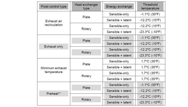
Typical Threshold Temperatures
Source: Indoor Humidity Assessment Tool, U.S. Environmental Protection Agency,
** To model preheat frost control, specify frost control type as 1‑None and select a pre-heat coil for the AHU controlled to the keep the air temperature above the frost threshold temperature.
This is the fraction of the simulation timestep when frost control will be invoked when the threshold temperature is reached. This setting is only used for the 2‑Exhaust air recirculation and 3‑Exhaust only frost control types. The value for this setting must be ≥ 0 and ≤ 1. The default time fraction is 0.083 (e.g., 5 min / 60 min) which is typical for Exhaust air recirculation frost control. Higher initial defrost time fractions (e.g., 0.167 = 10 min / 60 min) are typically required for Exhaust only frost control. For best results, you should obtain this information from the manufacturer.
This is the rate of increase in the defrost time fraction as the supply (outdoor) air inlet temperature falls below the threshold temperature. This field is only used for the 2‑Exhaust air recirculation and 3‑Exhaust only frost control types. The value for this setting must be ≥ 0. The default value is 0.012 (e.g., 0.72 min / 60 min per degree C temperature difference) which is typical for Exhaust air recirculation frost control. Higher values (e.g. 0.024 = 1.44 min / 60 min per °C temperature difference) are typically required for Exhaust only frost control. For best results, you should obtain this information from the manufacturer.
The total defrost time fraction is determined as follows:
Total defrost time fraction = Initial Defrost Time Fraction + Rate of Defrost Time Fraction Increase * (Tthreshold – Tsupply air inlet)
The model does not allow the total defrost time fraction to exceed 1.0 or be less than 0.
This is the schedule that determines whether or not the heat recovery device is available for each timestep of the simulation. A schedule value greater than 0 (usually 1 is used) indicates that the device can be on. A value less than or equal to 0 (usually 0 is used) denotes that the device must be off.
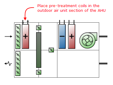
Pre-treatment heating and cooling coils, humidifiers and evaporative coolers can be included to ensure that the outside air is pre-conditioned before it enters the air handling unit. In v5.0 and earlier, pre-treatment coils were added through settings on the AHU dialog. In v5.2 and later they are instead added in the same way as for other AHU coils, by navigating to the AHU object and placing coils in the outdoor air unit section of the AHU. This allows more flexibility in the number and type of coils added and also in the way that they are controlled. See screenshot below.
You must also add a setpoint manager downstream of each coil added. To do this first navigate up to the supply side of the air loop. See screenshot below.
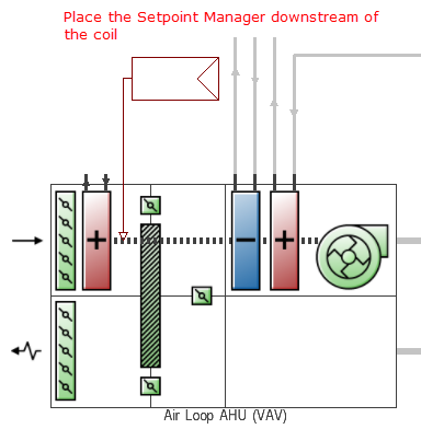
Note: Only 1-Scheduled type SPMs can be added for pre-treatment coils.