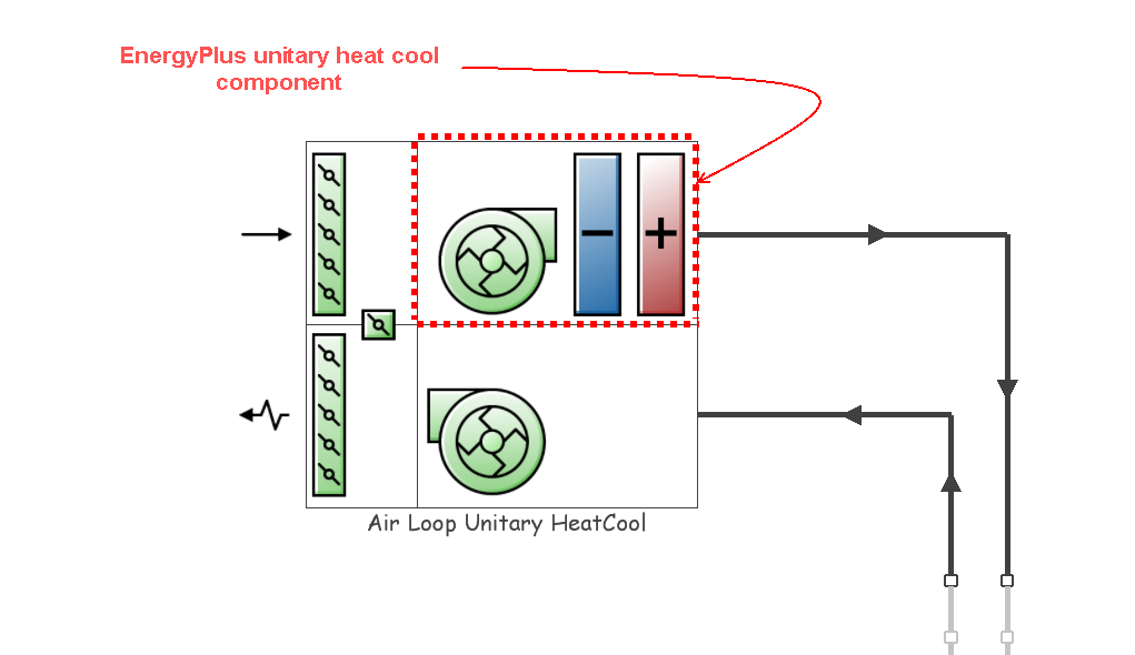
The unitary heat cool AHU incorporates an EnergyPlus unitary heat cool component, an outdoor air system (see Air Handling Unit Outdoor Air System), optional night cycle operation, an optional heat recovery system (see Heat Recovery), optional pre-heat and pre-cool coils and an optional extract fan. The unitary heat cool component itself comprises a supply fan, a DX cooling coil component and an electric heating coil component. If dehumidification control is selected, an electric reheat coil is automatically included.
Note: The Unitary Heat Cool AHU can only be added as part of a Unitary Heat Cool Air loop .
A detailed description of how Unitary air loops work is provided in the EnergyPlus Engineering Reference.
This is the name that you assign to the AHU which should be unique. If the supplied name is not unique, the software will automatically append a backslash and integer to ensure that there are no duplicate names.
This schedule contains information on the availability of the AHU for operation. A schedule value greater than 0 (usually 1 is used) indicates that the unit can be on during the hour. A value less than or equal to 0 (usually 0 is used) denotes that the unit must be off.
When this unit is unavailable (schedule values of 0) then all equipment contained within this AHU will also be switched off.
This is the design operating air outlet temperature (in °C or °F) when the unitary system is heating.
This is the air loop primary air design volumetric flow rate (in m3/s or ft3/min). This setting is auto-sizeable.
This setting defines the supply air flow rate leaving the heat pump (in m3/s or ft3/min) when the DX cooling coil is operating. Values must be greater than 0 or this field is auto-sizable.
This setting defines the supply air flow rate leaving the heat pump (in m3/s or ft3/min) when the DX heating coil and/or supplemental heater are operating. Values must be greater than 0 or this field is auto-sizable.
This setting defines the supply air flow rate leaving the heat pump (in m3/s or ft3/min) when neither cooling nor heating is required (i.e., DX coils and supplemental heater are off but the supply air fan operates). This setting is only used when the heat pump operating mode is specified as continuous fan operation (see Supply Air Fan Operating Mode Schedule). Values must be greater than or equal to zero, or this field is auto-sizable. If the heat pump operating mode is specified as continuous fan operation and this value is set to zero or this field is left blank, then the model assumes that the supply air flow rate when no cooling/heating is needed is equal to the supply air flow rate when the compressor was last operating (for cooling operation or heating operation).
Two fan types are available for selection in this AHU:
There are two options:
The supply air fan operating mode schedule can only be selected for On/Off fan types. The supply air fan operating mode may vary during the simulation based on time-of-day or with a change of season. Schedule values of 0 indicate that the unitary system supply air fan and the heating or cooling coil cycle on and off together to meet the heating or cooling load (sometimes referred to as an "AUTO" fan). Schedule values other than 0 denote that the supply fan runs continuously while the heating or cooling coil cycles to meet the load.
The default schedule is "Fan operation mode - Continuous" with a constant value of 1, i.e. that the supply fan runs continuously while the heating or cooling coil cycles to meet the load at all times. To obtain the AUTO fan configuration, select the "Fan operation mode - Cycling" schedule which has a constant value of 0.
An extract fan is included within all AHUs by default. This setting may be used to remove the extract fan from the AHU.
Note: This option is only available for Constant volume fan types. On/Off fans do not allow an extract fan to be included in the AHU and when this fan type is selected the Include extract fan check box will be disabled.
While the unitary heat cool AHU may be configured to serve multiple zones, system operation is controlled by a thermostat located in a single “control” zone. Click on the <Select zone> label and then click on the displayed ellipsis button to bring up the zone selector dialog. Select the zone supplied by the AHU where the thermostat controlling the unitary heat cool AHU is located.
There are two options for dehumidification control:
1‑None - meet sensible load only, no active de-humidification control;
2‑Cool Reheat - cool beyond the dry-bulb temperature set point as required to meet the high humidity setpoint.
Note: If 2‑Cool Reheat is used, a humidistat must be defined in one of the zones supplied by the AHU.
More information on controlling humidity is available in the Humidity control section.
See Night cycle description for Generic AHU
You can set up Mixed mode controls for the AHU to model optimal interaction between the natural ventilation system (Scheduled or Calculated) and the AHU.
Refer to the main HVAC tab Mixed Mode section for details on the available options.