Baffle
Construction
tab in model data under Construction header
You can model a multi-skin exterior heat transfer surface by making settings on the Constructions tab under the Baffle header at surface level. Baffle components consist of an outside baffle surface which is slightly detached from the main wall or roof forming a cavity which exchanges air with the outside environment.
Baffles are typically used to model naturally ventilated rainscreens and/or solar shading of exterior surfaces.
The constructions used to define the underlying wall/roof should reflect the construction of just the underlying surface. The data described here is used to describe the decoupled baffle layer and the characteristics of the cavity and openings for natural ventilation.
Tip: If the baffle covers only part of a surface, then surfaces without the baffle can be modelled as sub-surfaces which do not have natural vented cavities.
Tip: You can enter corresponding data for natural vented cavities on the Construction template dialog. If you need to apply settings to a large number of surfaces you may find the fasted way to do this is to use the Load data from template dialog, selecting the surfaces which have a baffle on the Target tab and selecting the Construction template with the appropriate natural vented cavity and construction settings.
 Technical Notes
- The corresponding EnergyPlus object is SurfaceProperty:ExteriorNaturalVentedCavity.
- The heat capacity of the outer baffle is ignored in the simulation since it is much lower than that of the underlying mass surface.
- The model involves predicting the rates that ambient air moves in and out of the cavity. Accurate modelling of these air flows would be extremely challenging and so the models provided through this object are simplistic engineering models based on discharge coefficients that are sensitive to wind and buoyancy effects. The accuracy depends on the values for, and applicability of, the discharge coefficients and unfortunately little research is available to help characterize these. The models should be considered rudimentary and the user is encouraged to explore different values for the coefficients in attempts to bound the importance of natural ventilation for the cavities. See the Engineering Reference for more details.
Area fraction of openings
This field is used to enter an area fraction for what part of the baffle consists of openings. The area of the openings will set to the product of this field and the sum of the area of the underlying surfaces.
Thermal emissivity of exterior baffle material
This field is used to enter the thermal emissivity of the baffler. This surface property is for longwave infrared radiation. The property is used for both sides of collector. Most painted materials have an emissivity of 0.9.
Solar absorptivity of exterior baffle
This field is used to enter the solar absorbtivity of the baffle. This surface property is for shortwave, solar radiation. The property is used for the front side of the baffle that faces the environment. Darker colors have a higher absorptivity. While black is the highest performance, other colors might be used to match the colour scheme of the rest of the façade.
Height Scale for buoyancy-driven ventilation
This field is used to enter a nominal height scale (m) for prediction of ventilation induced by buoyancy. This value ( ) is defined as the height from the midpoint of the lower opening to the neutral pressure level. Increasing the value will increase the ventilation rate due to buoyancy.
Effective thickness of cavity
This field is used to enter a nominal gap thickness (m) for the collector. If the baffle is corrugated, use the average depth. This distance value is only used when the collector is near horizontal to determine a length scale in the vertical direction for buoyancy calculations. For example, if the collector is mounted on a flat roof, its tilt-adjusted height is zero and the program will use this gap thickness as a length scale rather than the height from the previous field.
Ratio of actual to projected surface area
This field is used to enter a factor that accounts for the extra surface area resulting from and uneven baffle surface. Corrugations may be present to help stiffen the baffle or ventilated roofing tiles may have more surface are for convection heat transfer than the underlying surface. The projected surface area is obtained by the program from the (flat) underlying surfaces. If the baffle is flat then this ratio is 1.0. If the baffle is corrugated, then this ratio will be greater than one with a typical value might be 1.165.
Roughness of exterior surface
This field is used to describe the relative roughness of the baffle material which influences the the exterior convection coefficient. Select from:
- 1-Very rough
- 2-Rough
- 3-Medium rough
- 4-Medium smooth
- 5-Smooth
- 6-Very smooth
Effectiveness for perforations with respect to wind
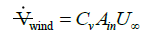
This field is used to enter a value for the coefficient used to determine natural air exchanges from wind. Wind will cause exterior air to move in and out of the cavity. Cv is an arbitrary coefficient used to model the effectiveness of openings and depends on opening geometry and the orientation with respect to the wind. Cv should probably be in the range 0.05 to 0.65. Increasing Cv will increase the amount of natural ventilation. The following equation shows how Cv is used in the program to predict the volumetric flow rate due to wind:
Discharge coefficient for openings with respect to buoyancy driven flow
This field is used to enter a value for the coefficient used to determine natural air exchanges from buoyancy. Stack or buoyancy effects will cause exterior air to move in and out of the cavity. Cd is an arbitrary discharge coefficient that depends on the geometry of the opening. Cd should probably be in the range 0.1 to 1.0. Increasing Cd will increase the amount of natural ventilation. The following equations show how Cd is used in the program to predict the volume flow rate due to buoyancy:
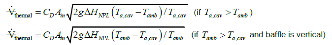
where  is the value input into the field above for the height scale for buoyancy-driven ventilation.