Cooling Design and Simulation tabs on Model Options dialog and Options tab on Simulation Options dialog.
Solar Options allow you to control aspects of the model related to solar gains.
The standard wall,floor, roof surfaces defining the current building provide shading but by default the other buildings on the site are excluded from the analysis. Use this option to include other buildings on the site as shading obstructions.
Cooling Design Calculations and Simulations both use this option but have separate Model option data.
Note: there is no way to simulate more than 1 building at a time. All external surfaces in buildings other than the current one are modelled as shading surfaces. If you need to model the adjacency of another building in contact with the current one, you can use the adiabatic adjacency option to model the touching surfaces.
Note: if one or more 'other buildings' are large/complex then you could generate a large number of shading elements and the simulation could be slow (even if the current building being simulated is simple).
When this option is selected, the program calculates the beam and sky solar radiation that is reflected from exterior surfaces and then strikes the building. These reflecting surfaces fall into 3 categories:
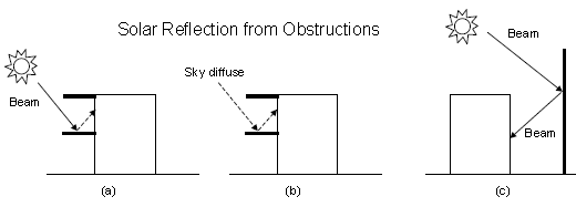
1. Shadowing surfaces. These are surfaces like overhangs or neighboring buildings (see below). These surfaces can have diffuse and specular (beam-to-beam) reflectance values derived from the material properties of the wall/windows.
Solar reflection from shadowing surfaces. Solid arrows are beam solar radiation; dashed arrows are diffuse solar radiation. (a) Diffuse reflection of beam solar radiation from the top of an overhang. (b) Diffuse reflection of sky solar radiation from the top of an overhang. (c) Beam-to-beam (specular) reflection from the façade of an adjacent highly-glazed building represented by a vertical shadowing surface.
2. Exterior building surfaces. In this case one section of the building reflects solar radiation onto another section (and vice-versa). See below. The building surfaces are assumed to be diffusely reflecting if they are opaque (walls, for example) and specularly reflecting if they are windows or glass doors. The reflectance values for opaque surfaces are calculated by the program from the Solar Absorptance and Visible Absorptance of the outer material layer of the surface’s construction. The reflectance values for windows and glass doors are calculated by the program from the reflectance properties of the individual glass layers that make up surface’s construction assuming no shading device is present and taking into account inter-reflections among the layers.
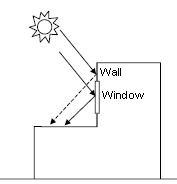
Solar reflection from building surfaces onto other building surfaces. In this example beam solar reflects from a vertical section of the building onto a roof section. The reflection from the window is specular. The reflection from the wall is diffuse.
3. The ground surface. Reflection from the ground is calculated even if theModel reflections and shading of ground reflected solar option is not used. But when it is used the ground plane is considered unobstructed, i.e., the shadowing of the ground by the building itself or by obstructions such as neighbouring buildings is ignored. This shadowing is taken into account if the reflections option is used. This is shown in diagrammatically below.
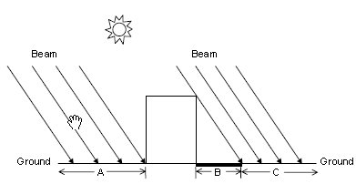
Shadowing from building affects beam solar reflection from the ground. Beam-to-diffuse reflection from the ground onto the building occurs only for sunlit areas, A and C, not from shaded area, B.
This option determines how EnergyPlus treats beam solar radiation and reflectance from exterior surfaces that strike the building and, ultimately, enter the zone. There are 3 choices:
1-Minimal shadowing - In this case, there is no exterior shadowing except from window and door reveals. All beam solar radiation entering the zone is assumed to fall on the floor, where it is absorbed according to the floor's solar absorptance. Any reflected by the floor is added to the transmitted diffuse radiation, which is assumed to be uniformly distributed on all interior surfaces. If no floor is present in the zone, the incident beam solar radiation is absorbed on all interior surfaces according to their absorptances. The zone heat balance is then applied at each surface and on the zone's air with the absorbed radiation being treated as a flux on the surface.
2-Full Exterior - in this case, shadow patterns on exterior surfaces caused by detached shading, wings, overhangs, and exterior surfaces of all zones are computed. As for Minimal shadowing, shadowing by window and door reveals is also calculated. Beam solar radiation entering the zone is treated as for 'Minimal shadowing' - all beam solar radiation entering the zone is assumed to fall on the floor, where it is absorbed according to the floor's solar absorptance. Any reflected by the floor is added to the transmitted diffuse radiation, which is distributed among interior surfaces according to view factors. If no floor is present in the zone, the incident beam solar radiation is absorbed on all interior surfaces according to their absorptance.
Note: If you use 2-Full Exterior you should make sure that all of your zones have a floor. If your building model has any zones of unusual shape without floors then the EnergyPlus simulation may not work because it will not have a surface to apportion solar gains to.
3-Full interior and exterior - this is the same as Full exterior except that instead of assuming all transmitted beam solar falls on the floor the program calculates the amount of beam radiation falling on each surface in the zone, including floor, walls and windows, by projecting the sun's rays through the exterior windows, taking into account the effect of exterior shadowing surfaces and window shading devices. If this option is used, you should be sure that the surfaces of the zone totally enclose a space. This can be determined by viewing the eplusout.dxf file with an external DXF viewer program.
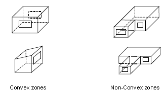
You should also be sure that the zone is convex. Examples of convex and non-convex zones are shown below. The most common non-convex zone is an L-shaped zone. A formal definition of convex is that any straight line passing through the zone intercepts at most two surfaces. Another definition is that a zone is convex if every surface in a zone can 'see' every other surface - no surfaces a 'round the corner' from each other. If the zone’s surfaces do not fully enclose a space or if the zone is not convex you should use Full exterior instead.
If you use 3-Full Interior and exterior the program will also calculate how much beam radiation falling on the inside of an exterior window (from other windows in the zone) is absorbed by the window, how much is reflected back into the zone, and how much is transmitted to the outside. In this calculation the effect of a shading device, if present, is accounted for.
Note: You must use 3-Full Interior and exterior to account for direct solar and light transmission through internal windows.
When the solar distribution selection is 3-Full interior and exterior (above) you can choose whether DesignBuilder is to check for non-convex zones. The DesignBuilder check for non-convex zones is very strict whereas the EnergyPlus check is less so. Generally EnergyPlus will tolerate a small degree of non-convex geometry. By default this option is switched on and the strict internal DesignBuilder convex check is carried out, but if the zones are only slightly non-convex you can switch off this check and allow EnergyPlus to continue calculations. You will probably receive error message 2 if you switch this option off and have non-convex zones.
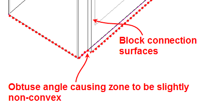
One common reason for the strict DesignBuilder check to flag a zone as being non-convex even when at first sight it is convex is the use of block connection geometry. In the above example of a double skin facade (DSF) cavity zone, you can see when zooming right in on the corner of a set of block connection surfaces that these surfaces cause obtuse angles to the zone geometry resulting in very slight non-convex geometry. These are exactly the sort of small deviations from convex that the DesignBuilder checker will fail and the EnergyPlus checks will pass. In this case it is perfectly safe to switch off this check to allow EnergyPlus calculations to proceed.
Enter the number of days (1-365) covered by each shadowing calculation.
Enter 1 if you want shadowing to be calculated every day (for greater detail but slower calculations).