Trombe walls are passive solar devices designed for thermal storage and delivery. A Trombe wall consists of a thick wall (150mm to 300mm) [8" to 16"] faced with a selective surface solar absorber, air gap, and high transmissivity glass pane. Trombe walls are usually South facing (in the Northern Hemisphere) for maximum sun exposure. An overhang above the wall is used to decrease exposure in the summer when the sun is high in the sky and heating is not required, yet still allows for full exposure in the winter when the sun is low in the sky and heating is desirable. In DesignBuilder, there is no Trombe wall object per se; rather, it is composed of other standard building components. This approach provides flexibility in specifying the various wall parameters and allows the freedom to explore unusual configurations.
To simulate the Trombe wall, a narrow zone is coupled to the desired surface via an interzone partition. The depth of the zone corresponds to the size of the air space usually 18mm to 150mm (¾" to 6"). In most cases the Trombe zone will be a sealed zone with no ventilation. The exterior wall of the Trombe zone contains a single or double-pane window. Optimally, the window covers nearly all of the wall area and has a very high transmissivity to allow the maximum amount of solar flux into the Trombe zone. Frames and dividers can be defined as usual for the window. The interior wall is usually constructed of very thick masonry materials with a solar absorber surface as the innermost layer of the wall. The absorber is a selective surface material with very high absorptivity and very low emissivity, e.g. copper with a special black surface treatment. It is important to make sure the Solar Distribution is set to 3-Full Interior and Exterior so that the majority of the solar flux is directed on the absorber surface and not just on the very small area of the Trombe zone floor.
The Zone type on the Activity tab should be set to 3-Cavity at zone level in the Trombe wall cavity zone and this causes the following further changes to be made to the model:
Finally, an overhang should be attached to the Trombe zone to control the amount of seasonal sun exposure. There is considerable freedom to experiment with different materials, sizes, and configurations.
Passive Trombe walls perform without the assistance of any additional mechanical equipment. Most Trombe walls are passive Trombe walls. They can be either sealed or naturally ventilated. For a sealed or unvented Trombe wall, the Zone Inside Convection Algorithm should be set to 5-Cavity. This algorithm correctly calculates the convection coefficients for a narrow sealed vertical cavity based on the ISO 15099 standard.
The EnergyPlus modeling approach for the sealed passive Trombe wall has been validated with experimental data (Ellis 2003). For a naturally ventilated Trombe wall, there is no built-in algorithm for calculating the correct convection coefficients on the inside of the cavity walls. One option is to use the 1-Detailed Inside convection algorithm. This algorithm takes into account some natural convection effects but is intended for a normal sized room.
You can define holes and vents through the Trombe wall by drawing them on at surface level. Vent openings can be scheduled and controlled by internal temperature.
You can also model mechanically ventilated Trombe walls by using Detailed HVAC and specifying the Trombe wall cavity zone as a plenum zone.
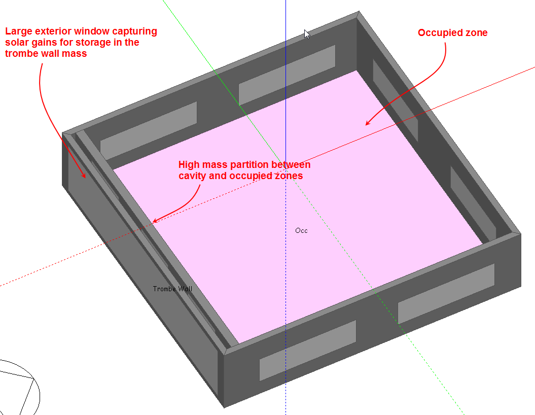
A Trombe wall example model is provided with DesignBuilder. This is a simple 2 zone building, one occupied zone, the other zone representing the cavity. The screen shot below of the example building shows the 2 zones and the high mass partition between them.
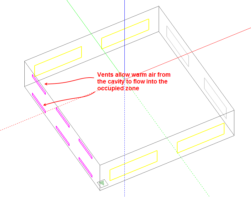
The screenshot below shows the configuration of vents in the partition between the 2 zones allowing warm air to move into the occupied space. The calculated natural ventilation model option has been used to allow detailed calculation of air movement between the 2 zones.
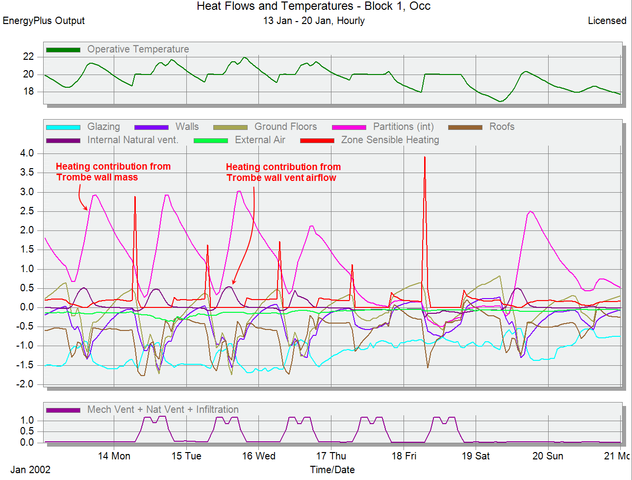
The hourly results below are for the occupied zone and illustrate the delayed heating effect of the Trombe wall mass on the occupied zone during the evening and also the lesser but more instantaneous heating effect of the warm air entering through the vents during the daytime.