![]() Boiler:HotWater
Boiler:HotWater
Used in:
- Hot water loop, supply side
|
|
|
Used in:
|
Boilers provide hot water to hot water heating coils, hot water radiators, heated floors, baseboards etc. The fuel consumed by the boiler is based on a nominal thermal efficiency value. A normalised efficiency performance curve can additionally be used to more accurately represent the performance of non-electric boilers, but is not a required input.
Boilers can be placed using the Add Boiler tool when you are located in a hot water supply loop.
To edit an existing boiler go to the Hot water supply loop (HVAC System > Hot water loop > Supply loop) level where the boiler is placed, click on the boiler icon to highlight it then either right click and select the Edit selected component menu option or, when using Learning mode, click on the Edit icon in at the top of the info panel.
The auto-generated name of the boiler can be edited.
Use this browse option to select a boiler from the EnergyPlus boilers database.
Select the type of fuel used by the boiler. The fuel type can be one of:
9-Other fuel 1 and 10-Other fuel 2 can be used for representing biofuels such as biomass and biogas for example.
This numeric field contains the nominal operating capacity of the boiler (in W or Btu/h). The boiler nominal capacity may be autosized.
This choice field determines how the boiler operates with respect to the intended fluid flow through the device. There are three choices:
In all cases the operation of the external plant system can also impact the flow through the boiler - for example if the relative sizes and operation are such that flow is restricted and the requests cannot be met.
For variable flow chilled water loops these options are available:
For constant flow chilled water loops these options are available:
The type of loop (variable/constant flow) can be changed by modifying the Plant loop flow type on the Hot water plant loop dialog.
Note: When the 2-Leaving setpoint modulated option is selected then you must add an extra Setpoint manager immediately downstream of the boiler hot water outlet to define the temperature of the water supplied.
This optional numeric field contains the parasitic electric power (in W or Btu/h) consumed by a forced draft fan or other electrical device associated with the boiler. This parasitic electric load is consumed whenever the boiler is operating, and the model assumes that this parasitic power does not contribute to heating the water. The minimum value for this field is 0.0.
The sizing factor is used when the boiler design inputs are autosized. In this case the autosizing results are multiplied by this additional sizing factor. The usual value to enter is 1.0.
The inputs that would be altered by the sizing factor are: Nominal capacity and Design water flow rate.
The most common use of the sizing factor is for sizing boilers to meet only part of the design load while continuing to use the autosizing feature. For example when a set of boilers is chained together to supply hot water to a plant loop, this sizing factor can be used to indicate the proportion of the load to be met by each boiler.
See also the section on Autosizing HVAC Components
The EnergyPlus boiler model is based the following two equations:
Theoretical Fuel Consumption = Boiler Load / Nominal Thermal Efficiency
Fuel Used = Theoretical Fuel Consumption / Normalised Boiler Efficiency Curve Output
This is the heating efficiency (as a fraction between 0 and 1) of the boiler’s burner relative to the higher heating value (HHV) of fuel at a part load ratio of 1.0. Manufacturers typically specify the efficiency of a boiler using the higher heating value of the fuel. For the rare occurrences when a manufacturers (or particular data set) thermal efficiency is based on the lower heating value (LHV) of the fuel, multiply the thermal efficiency by the lower-to-higher heating value ratio. For example, assume a fuel’s lower and higher heating values are approximately 45,450 and 50,000 kJ/kg, respectively. For a manufacturers thermal efficiency rating of 0.90 (based on the LHV), the nominal thermal efficiency entered here is 0.82 (i.e. 0.9 multiplied by 45,450/50,000).
Note: The overall boiler efficiency used during the simulation will be the product of the Nominal thermal efficiency and the output of Normalized boiler efficiency performance curve (below).
This field is used to control which value for hot water temperature is used when evaluating the Normalized boiler efficiency performance curve specified in the next field (if applicable). There are two options:
This field is only used if type of curve is one that uses temperature as a independent variable.
This field contains the Curve which describes the normalized heating efficiency (as a fraction of nominal thermal efficiency) of the boiler’s burner. If the <None> linear curve is selected, the nominal thermal efficiency is assumed to be constant (i.e., Fuel Used is equal to the Theoretical Fuel Use in the equation above). When a boiler efficiency curve is used, the curve may be any valid curve with 1 (PLR) or 2 (PLR and boiler outlet water temperature) independent variables. A tri-quadratic curve object is not allowed since it uses 3 independent variables. The linear, quadratic, and cubic curve types may be used when the boiler efficiency is only a function of boiler part-load ratio (PLR). When this type of curve is used, the boiler should operate at (or very near) the design boiler water outlet temperature. Other curve types may be used when the boiler efficiency is a function of both PLR and boiler water temperature. Examples of valid single and dual independent variable equations are shown below. For all curve types PLR is always the x independent variable. When using 2 independent variables, the boiler outlet water temperature (Toutlet) is always the y independent variable.
Linear: Eff = A0 + A1*PLR
Quadratic: Eff = A0 + A1*PLR + A2*PLR2
Cubic: Eff = A0 + A1*PLR + A2*PLR2 + A3*PLR3
BiQuadratic: Eff = A0 + A1*PLR + A2*PLR2 + A3* Tw + A4* Tw 2 + A5*PLR* Tw
QuadraticLinear: Eff = A0 + A1*PLR + A2*PLR2 + A3* Tw + A4*PLR* Tw + A5*PLR2* Tw
BiCubic: Eff=A0+A1*PLR+A2*PLR2+A3*Tw+A4*Tw2+A5*PLR*Tw+A6*PLR3+A7*Tw3+A8*PLR2*Tw+A9*PLR* Tw2
where:
Eff = normalized boiler efficiency
PLR = boiler part-load ratio
Tw = boiler (outlet) water temperature [ºC]
When using the normalized efficiency performance curve, if all coefficients are not required, simply set the unused coefficients to 0. For example, an electric boiler could be modelled by setting the nominal thermal efficiency to a value in the range of 0.96 to 1.0. Coefficient 0 in the normalized efficiency performance curve would equal 1 and all other coefficients would be set to 0. Coefficients for other types of non-electric boilers would set a combination of the available coefficients to non-zero values.
The graph below (reproduced with permission from CIBSE) illustrates the range of typical efficiency for different types of boiler.
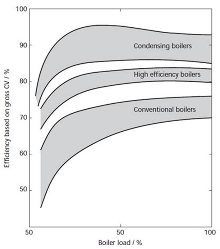
CIBSE Guide B Fig 1.4
This numeric field contains the maximum design water volumetric flow rate (in m3/sec or gal/min). This should be the largest flow rate than can be heated to the design outlet temperature. This field is autosizable.
This numeric field contains the outlet temperature upper limit (in °C or °F). It is used to cap the output from the boiler to avoid the boiler water outlet temperature from getting too high when the boiler is operating at less than the design flow rate, or when the return water temperature is relatively high. It is similar to the Leaving chilled water lower temperature limit for chillers.
Warning: The Water outlet upper temperature limit must be at least 5°C higher than the design supply loop outlet heating setpoint temperature to avoid the boiler cutting out during the simulation. Using temperatures equal to the supply loop design outlet temperature typically prevents boiler operation completely. You are advised to leave this setting at 100°C even when supplying hot water at much lower temperatures.
This numeric field contains the minimum part load ratio. If the ratio of demand to boiler nominal capacity is less than the minimum part load ratio, then the Min PLR will determine the operating PLR. The expected range is between 0 and 1.
This numeric field contains the maximum part load ratio. If the ratio of demand to boiler nominal capacity is greater than the maximum part load ratio, then the Max PLR will determine the operating PLR. This value may exceed 1, but the normal range is between 0 and 1.1.
This numeric field contains the optimum part load ratio, i.e. is the part load ratio at which the boiler performs at its maximum efficiency. It is used in the load management calculations when the Plant loop Load distribution scheme is set to 2-Optimal. A typical value will be 1, but for condensing gas boilers, the optimum part load ratio is much lower at about 0.3.
HVAC,Average,Boiler Heating Output Rate [W]
HVAC,Sum,Boiler Heating Output Energy [J]
Zone,Meter,Boilers:EnergyTransfer [J]
HVAC,Average,Boiler Water Inlet Temp [C]
HVAC,Average,Boiler Water Outlet Temp [C]
HVAC,Average,Boiler Water Mass Flow Rate [kg/s]
HVAC,Average,Boiler Parasitic Electric Power [W]
HVAC,Sum,Boiler Parasitic Electric Consumption [J]
HVAC,Average,Boiler Part-Load Ratio
One of the following blocks will be applicable based on fuel type:
HVAC,Average,Boiler Electric Consumption Rate [W]
HVAC,Sum,Boiler Electric Consumption [J]
Zone,Meter, Electricity:Plant [J]
Zone,Meter,Heating:Electricity [J]
HVAC,Average,Boiler Gas Consumption Rate [W]
HVAC,Sum,Boiler Gas Consumption [J]
Zone,Meter,Gas:Plant [J]
Zone,Meter,Heating:Gas [J]
HVAC,Average,Boiler Propane Consumption Rate [W]
HVAC,Sum,Boiler Propane Consumption [J]
Zone,Meter, Propane:Plant [J]
Zone,Meter,Heating:Propane [J]
HVAC,Average,Boiler FuelOil#1 Consumption Rate [W]
HVAC,Sum,Boiler FuelOil#1 Consumption [J]
Zone,Meter, FuelOil#1:Plant [J]
Zone,Meter,Heating:FuelOil#1 [J]
HVAC,Average,Boiler FuelOil#2 Consumption Rate [W]
HVAC,Sum,Boiler FuelOil#2 Consumption [J]
Zone,Meter, FuelOil#2:Plant [J]
Zone,Meter,Heating:FuelOil#2 [J]
HVAC,Average,Boiler Coal Consumption Rate [W]
HVAC,Sum,Boiler Coal Consumption [J]
Zone,Meter,Coal:Plant [J]
Zone,Meter,Heating:Coal [J]
HVAC,Average,Boiler Diesel Consumption Rate [W]
HVAC,Sum,Boiler Diesel Consumption [J]
Zone,Meter, Diesel:Plant [J]
Zone,Meter,Heating:Diesel [J]
HVAC,Average,Boiler Gasoline Consumption Rate [W]
HVAC,Sum,Boiler Gasoline Consumption [J]
Zone,Meter, Gasoline:Plant [J]
Zone,Meter,Heating:Gasoline [J]
These outputs are the heating output (load) of the boiler. Energy is metered on Boilers:EnergyTransfer, EnergyTransfer:Plant, and EnergyTransfer:Facility.
These outputs are the hot water inlet and outlet temperatures and flow rate for the boiler.
This output is the operating part-load ratio of the boiler. The part-load ratio is calculated as the boiler load divided by the boiler nominal capacity. The part-load ratio is limited by the minimum and maximum part-load ratio inputs specified by the user.
These outputs are the energy input to the boiler. Valid fuel types are: Electric, Gas (natural gas), Propane, FuelOil#1, FuelOil#2, Coal, Diesel, and Gasoline. Consumption is metered on Heating:<FuelType>, <FuelType>:Plant, and <FuelType>:Facility.
These outputs are the parasitic electric power and parasitic electric consumption associated with the boiler. Used when simulating a forced draft fan or other electric component. Consumption is metered on Heating:Electricity and Electricity:Plant.