Autosizing HVAC Components
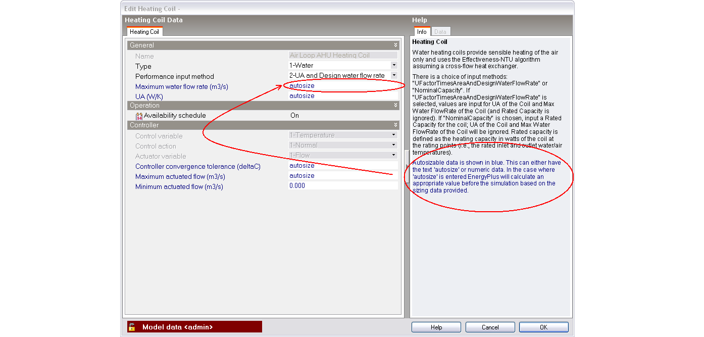
In many cases, HVAC component sizes can be autosized by EnergyPlus. All settings that can be autosized are displayed in dark blue on the component edit dialogs. The special keyword Autosize must typed into the edit control on the component edit dialog if a setting is to be autosized.
For example, for a hot water coil, the Maximum water flow rate can be autosized:
Autosizing in EnergyPlus
EnergyPlus is able to automatically size many HVAC components based on user-specified building configuration and design external conditions.
By default DesignBuilder automatically provides data on 2 sizing periods, one for winter, the other for summer for sizing heating and cooling equipment respectively. If multiple summer design months have been selected these will all be used in the summer simulation cooling autosizing as well. EnergyPlus uses this design day weather data to specify outside conditions when autosizing HVAC components.
Information on how zone load sizing is to be carried out can be entered for each zone (on the HVAC zone dialog). Also data governing how air loops are to be sized can be entered for each air system on the Air loop dialog. Likewise sizing data for plant and condenser loops is entered on Plant loop dialogs.
Other than zone thermostat setpoints, the sizing calculations generally know nothing about the system control inputs defined on Setpoint managers and availability schedules. You must coordinate the sizing inputs on the HVAC zone and air loop dialogs with the actual simulation control inputs.
The sizing calculations only recognize the presence of central heating and cooling coils, preheat and precool coils and reheat coils. These are assumed to deliver the various supply temperatures specified in the Air loop and HVAC Zone objects. The impact of their sub-components such as heat recovery, dehumidifiers, fans, and pumps are not accounted for in the sizing calculations.
Note: The Detailed HVAC autosizing calculations referred to on this page are not to be confused with Heating and Cooling design calculations which use separate simpler data entry from the HVAC tab. No Detailed HVAC data is used for Heating and Cooling design calculations, which are based on the EnergyPlus Ideal loads system.
Schedules and Sizing
Close attention should be paid to Schedules. When using 7/12 schedules you must make sure that the appropriate Design day definition is made to ensure that they reflect appropriate summer and winter design days respectively. Likewise Compact schedules provide the SummerDesignDay and WinterDesignDay day types and these must be set up correctly.
Some commonly used applications of summer and winter design days in schedules are:
- Setting internal loads (lights, equipment, occupancy) to maximum all day for cooling and to zero all day for heating;
- Setting heating and cooling thermostat set points to constant values (no set up or set back);
- Setting heating and cooling equipment to be always on for design days.
None of these applications are necessarily recommended but these and other uses of the special summer/winter design day schedules may prove useful for specific situations.
Some examples of common mistakes with design day data in schedules are:
- Using a schedule such as the predefined On schedule for operating internal gains equipment such as computers or lights. Internal gains must not be included in heating sizing calculations because the size of the heating equipment must be calculated without consideration of any contribution from internal gains. Including such gains usually results in undersizing of heating zone equipment and/or plant. Internal gains must of course be included in cooling sizing so should operate for the SummerDesignDay.
- Selecting a Heating operation schedule on the HVAC tab with options indicating the schedule to be off for the WinterDesignDay. Or selecting a Cooling operation schedule on the HVAC tab with options indicating the schedule to be off for the SummerDesignDay. Likewise when using the 2-Detailed HVAC activity data model option the heating and cooling setpoint schedules selected on the HVAC zone dialog must operate on their respective design day periods.
Sizing Factors
There are generally 2 areas of input where the user can impose sizing factors.
- In HVAC zone sizing data, the user can specify heating and cooling sizing factors for a specific zone. These factors are applied to the calculated zone design loads and air flow rates.
- For some plant components (all central chillers, boilers and cooling towers) the user can specify a sizing factor that modifies the autosized component capacity and flow rates. These factors are applied after zone sizing factors. They are primarily used to split the design load between multiple components. These sizing factors can change the autosizing of the associated loops and pumps. The following rules define the effect of plant component sizing factors on loops and pumps.
- For supply side branches, the sizing factors of all components in series on the branch are summed and the result becomes the branch sizing factor. If there is a branch pump, its autosized design flow rate is multiplied by the branch sizing factor.
- For each loop, if the average of the branch sizing factors is less than 1, the loop sizing factor is set equal to the sum of he branch sizing factors. If the average is greater than 1, the loop sizing factor is set equal to the maximum of the branch sizing factors. The loop sizing factor is applied to the loop design flow rate (if autosized) and to the loop pump flow rate (if autosized).
Mixing User-Specified and Autosized Inputs
Mixed user-specified and autosized inputs can be successfully used if the following points and suggestions are followed.
- Each component is autosized independently. Thus user input for a flow rate in one component will have no effect on other components’ autosized flow rates. For instance, specifying the chilled water loop pump’s rated flow rate will have no effect on the autosizing of the chiller’s design evaporator flow rate or on the plant loop’s autosized maximum loop flow rate.
- Within a component it is best to autosize all inputs or enter specified values for all inputs. For example, in a chiller, if only the nominal capacity is user-specified, the autosized chilled water flow rate may not be consistent with the specified capacity.
- Sizing information flows only from the sizing data on the HVAC zone, Air loop and Plant loop dialogs to the components. The sizing calculations have no knowledge of user-specified values in a component. The only exception to this rule is that plant loop sizing will collect all component design water flow rates whether autosized or user-specified.
- To specify a particular zone or system air flow rate use the HVAC Zone and Air Loop data rather than in the individual components.
- The plant loop flow rates are sized from the total design demand of the components connected to each loop. The components demanding water need not be autosized for the plant loop autosizing to work successfully. So the user could specify all the air side components and autosize all the plant loops and plant components. Or specify the chilled water loop flow rate, chilled water pump inputs and chiller inputs and let the condenser loop and tower autosize.
Zone design flow rate inputs
In EnergyPlus the autosizing calculations start with a calculation of the zone design air flow rates using zone by zone design day simulations. The resulting zone design air flow rates and daily air flow sequences are used in the subsequent HVAC and central plant air and fluid flow design calculations and in the component autosizing calculations. The user can override or change the calculated zone design air flow rates in various ways.
- The user can specify a separate zone level Zone sizing factor for heating and cooling for each HVAC zone object.
- For each zone the user can input a Cooling design air flow rate and/or a Heating design air flow rate (and specify Cooling design air flow method = 1-Flow/Zone and Heating design air flow method = 1-Flow/Zone). These user inputs override the calculated values. The program divides the user input cooling or heating design air flow rate by the calculated values and uses the result as a zone sizing factor to multiply all the elements in the design heating and cooling air flow and load sequences. From this point the design calculations proceed as usual.
System design flow rate inputs
Using the results of the zone design air flow rate calculation (including any user input or altered flow rates) EnergyPlus proceeds to calculate central air system flow rates and cooling and heating loads. The results of this calculation can be overridden by setting the Air loop Cooling design air flow method to be 2-Flow/System and input a value for Cooling design air flow rate. Similarly for heating specify the Heating design air flow method to be 2-Flow/System and input a value for Heating design air flow rate.
HVAC Sizing Tips
To help achieve successful autosizing of HVAC equipment, note the following general guidelines:
- Begin with everything fully autosized (no user-specified values) and get a working system before trying to control any specifically sized components.
- You must coordinate system controls with sizing inputs. For example, if the Air loop Central cooling design supply air temperature is set to 13°C, you must make sure that the corresponding setpoint manager for the central cooling coil controls to the same 13°C as design conditions. EnergyPlus does not cross-check these inputs. The HVAC autosizing calculations use the sizing information in the Air loop and HVAC zone data. The simulation uses the information in controllers and setpoint managers.
- User-specified flow rates will only impact the sizing calculations if entered in the Air loop and HVAC zone data. Sizing information flows only from the sizing objects to the components. The sizing calculations have no knowledge of user specified values in a component. The only exception to this rule is that plant loop sizing will collect all component design water flow rates whether autosized or user specified.
- The zone thermostat schedules determine the times at which design loads will be calculated. All zone-level schedules (such as lights, electric equipment, infiltration) are active during the sizing calculations (using the day type specified for the sizing period). System and plant schedules (such as availability managers and component schedules) are unknown to the sizing calculations. To exclude certain times of day from the sizing load calculations, use the thermostat setpoint schedules for SummerDesignDay and/or WinterDesignDay. For example, setting the cooling setpoint schedule to 99°C during night-time hours for the SummerDesignDay day type will turn off cooling during those hours.
Differences between Autosizing Simulations and Cooling Design Calculations
In general the zone heating and cooling loads displayed in the "HVAC Sizing Summary" table for the autosizing simulations should match closely with the equivalent values displayed on the Cooling design screen on the Summary tab. However some differences may be observed due to one or more of:
- When using Detailed HVAC and the Detailed HVAC activity data, the simulation setpoints and schedules are defined separately on the HVAC zone dialog and can easily be different to the setpoints defined on the Activity tab and to the schedules defined on the HVAC tab. When using the default Simple HVAC activity data option this difference is much less likely to occur.
- The mechanical ventilation settings are defined on the HVAC tab for heating and cooling design calculations but they are defined on the Air loop dialog for autosizing simulations.
- The conditions of the supplied air is defined on the HVAC zone dialog for autosizing simulations whereas the data on the HVAC tab under Supply air conditions headers is used for heating and cooling design calculations.
- Cooling design calculations are run using 2 timesteps per hour whereas the cooling autosizing simulations are run using the number of timesteps selected for the simulation. The timestep difference doesn't arise for heating design where the inside and outside conditions are static.
- The WinterDesignDay settings control the operation for the heating autosizing simulations, whereas for Heating design calculations, fixed values are always used and there is less scope for obtaining "surprising" results. E.g. there is no way to include internal gains from occupants and equipment, whereas it is possible to include these gains (deliberately or inadvertently) in heating autosizing simulations through compact schedule settings.
- When the Calculated natural ventilation model option is selected this is used in autosizing simulations (if the relevant schedules allow it) whereas for Cooling design calculations the scheduled natural ventilation settings are used (if natural ventilation is enabled).
- Heat recovery can be activated or not for Cooling design calculations whereas it is not included when sizing zone loads in autosizing simulations.