![]() Chiller:Electric:ReformulatedEIR
Chiller:Electric:ReformulatedEIR
Used in:
- Chilled water loop, supply side
|
|
|
Used in:
|
The Reformulated EIR chiller is an empirical model similar to the Chiller EIR. The model uses performance information at reference conditions along with three curve fits for cooling capacity and efficiency to determine chiller operation at off-reference conditions. The model has the same capabilities as the Chiller EIR, but can potentially provide significant accuracy improvement for variable-speed compressor drive and variable condenser water flow applications. Chiller performance curves can be generated by fitting manufacturer’s catalog data or measured data.
Tip: Performance curves developed from manufacturer’s performance data are provided in the Chiller templates.
This chiller model can be used to predict the performance of various chiller types (e.g., reciprocating, screw, scroll, and centrifugal) with water-cooled condensers. The main difference between this model and the Chiller EIR model is the condenser fluid temperature used in the associated performance curves: the Chiller Reformulated EIR model uses the leaving condenser water temperature while the Chiller EIR model uses the entering condenser water temperature. Although this model can provide more accurate prediction than the Chiller EIR model, it requires more performance data to develop the associated performance curves (at least 12 points from full-load performance and 7 points from part-load performance).
Note: Reformulated Chiller EIR components and their associated performance curve objects are developed using performance information for a specific chiller and should normally be used together for an EnergyPlus simulation. Changing the object input values, or swapping performance curves between chillers, should be done with caution. For example, if the user wishes to
model a chiller size that is different from the reference capacity, it is highly recommended that the
reference flow rates be scaled proportionately to the change in reference capacity.
The auto-generated name of the chiller can be edited.
Use this browse option to select a chiller from the EnergyPlus chiller database whose performance data you wish to copy to your chiller.
The type of chiller can be one of these options:
Note: The Chiller type cannot be edited directly. To help you to ensure that appropriate performance curves are used, you must either load a new chiller template of the type required or add a new chiller, selecting the appropriate type from the drop list.
This numeric field contains the reference cooling capacity of the chiller (in W or Btu/h). This should be the capacity of the chiller at the reference temperatures and water flow rates defined below. Alternatively, this field can be autosized.
This numeric field contains the chiller’s coefficient of performance which is multiplied by the output of the chiller performance curves described below. This value should not include energy use due to pumps or cooling tower fans. This COP should be at the reference temperatures and water flow rates defined below.
This numeric input represents the fraction of compressor electrical energy consumption that must be rejected by the condenser. Enter a value of 1.0 when modelling hermetic chillers. For open chillers, enter the compressor motor efficiency. This value must be greater than 0.0 and less than or equal to 1.0, with a default value of 1.0.
This option determines how the chiller operates with respect to the intended fluid flow through the device’s evaporator. There are three choices for specifying operating modes for the intended flow behaviour:
In all cases the operation of the external plant system can also impact the flow through the chiller - for example if the relative sizes and operation are such that flow is restricted and the requests cannot be met.
For variable flow chilled water loops these options are available: 2-Leaving setpoint modulated and 3-Not modulated.
For constant flow chilled water loops these options are available: 1-Constant flow and 3-Not modulated.
The type of loop (variable/constant flow) can be changed by modifying the Plant loop flow type on the Chilled water plant loop dialog.
Note: When the 2-Leaving setpoint modulated option is selected then you must add an extra Setpoint manager immediately downstream of the chiller chilled water outlet to define the temperature of the water supplied.
The sizing factor is used when the chiller design inputs are autosized. In this case the autosizing results are multiplied by this additional sizing factor. The usual value to enter is 1.0.
The inputs that would be altered by the sizing factor are: Reference capacity, Reference chilled water flow rate and Reference condenser water flow rate.
The most common use of the sizing factor is for sizing chillers to meet only part of the design load while continuing to use the autosizing feature. For example when a set of chillers is chained together to supply chilled water to a plant loop, this sizing factor can be used to indicate the proportion of the load to be met by each chiller.
See also the section on Autosizing HVAC Components
This numeric field contains the chiller’s reference leaving chilled water temperature (in °C or °F). The default value is 6.67°C.
This numeric field contains the chiller’s reference leaving condenser water temperature (in °C or °F). The default value is 35°C.
This numeric field contains the lower limit for the leaving chilled water temperature (in °C or °F). This temperature acts as a cut off for heat transfer in the evaporator, so that the fluid doesn’t get too cold. The default value is 2˚C.
For a variable flow chiller this is the maximum water flow rate and for a constant flow chiller this is the operating water flow rate through the chiller’s evaporator. The units are (in m3/s or gal/min). This numeric input field must be greater than zero, or it can be autosized.
This numeric field contains the chiller’s operating condenser water flow rate (in m3/s or gal/min). This numeric input field must be greater than zero, or it can be autosized.
Note: For water cooled chillers, EnergyPlus sets the condenser fluid flow rate to the maximum value whenever the chiller is operating. The Chiller flow mode only affects the chiller evaporator flow rate.
The Bi-quadratic performance curve parameterizes the variation of the cooling capacity as a function of the leaving chilled water temperature and the leaving condenser fluid temperature. The output of this curve is multiplied by the reference capacity to give the cooling capacity at specific temperature operating conditions (i.e., at temperatures different from the reference temperatures). The curve should have a value of 1.0 at the reference temperatures and flow rates specified above. The bi-quadratic curve should be valid for the range of water temperatures anticipated for the simulation.
Note: This option is not shown on the DesignBuilder dialog but may be in the future.
In EnergyPlus this option determines which type of the Electric Input to Cooling Output Ratio Function of Part Load Ratio Curve is used in the chiller modelling. Two curve types are available:
The Bi-quadratic or Bi-cubic performance curve is used to define the Electric Input to Cooling Output Ratio Function of Part Load Ratio. The form of this curve is based on the input for Electric Input to Cooling Output RatioFunction of Part Load Ratio Curve Type. The curve object type should be that parameterizes the variation of the energy input to cooling output ratio (EIR) as a function of the leaving chilled water temperature and the leaving condenser water temperature. The EIR is the inverse of the COP.
The output of this curve is multiplied by the reference EIR (inverse of the reference COP) to give the EIR at specific temperature operating conditions (i.e., at temperatures different from the reference temperatures). The curve should have a value of 1.0 at the reference temperatures and flow rates specified above. The curve should be valid for the range of water temperatures anticipated for the simulation (otherwise the program issues warning messages).
This Bi-quadratic performance curve parameterizes the variation of the energy input ratio (EIR) as a function of the leaving condenser water temperature and the part-load ratio (EIRfTPLR). The EIR is the inverse of the COP, and the part-load ratio is the actual cooling load divided by the chiller’s available cooling capacity.
This curve is generated by dividing the operating electric input power by the available full-load capacity (do not divide by load) at the specific operating temperatures. The curve output should decrease from 1 towards 0 as part-load ratio decreases from 1 to 0. The output of this curve is multiplied by the reference full-load EIR (inverse of the reference COP) and the Energy Input to Cooling Output Ratio Function of Temperature Curve to give the EIR at the specific temperatures and part-load ratio at which the chiller is operating. This curve should have a value of 1.0 at the reference leaving condenser water temperature with the part-load ratio equal to 1.0.
An ideal chiller with the same efficiency at all part-load ratio’s would use a performance curve that has a value of 0 when the part-load ratio equals 0 (i.;e., a line connecting 0,0 and 1,1 when plotted as EIRfTPLR versus PLR), however, actual systems can have part-load EIR’s slightly above or below this line (i.e., part-load efficiency often differs from rated efficiency). The bicubic curve should be valid for the range of condenser water temperatures and part-load ratios anticipated for the simulation (otherwise the program issues warning messages).
Note: Although a bicubic curve requires 10 coefficients, coefficients 7, 9 and 10 are typically not used in the performance curve described here and should be entered as 0 unless sufficient performance data and regression accuracy exist to justify the use of these coefficients. Additionally, coefficients 2, 3, and 6 should not be used unless sufficient temperature data is available to accurately define the performance curve (i.e., negative values may result from insufficient data).
During the simulation the electric power consumption of the compressor is calculated using:
Qcompressor = (Qref / CoPref) * CAPFT * EIRFT * EIRPLR
Where CAPFT, EIRFT and EIRPLR are the outputs from the 3 curves above.
If you have manufacturers data you can generate the inputs for these 3 curves using the spreadsheet provided free by EnergyPlus called Chiller_PerformanceCurve_Coefficients.xls. When using this spreadsheet to generate inputs for EIRPLR note that the coefficients are read from the spreadsheet into the DesignBuilder Quadratic Curve dialog as follows:
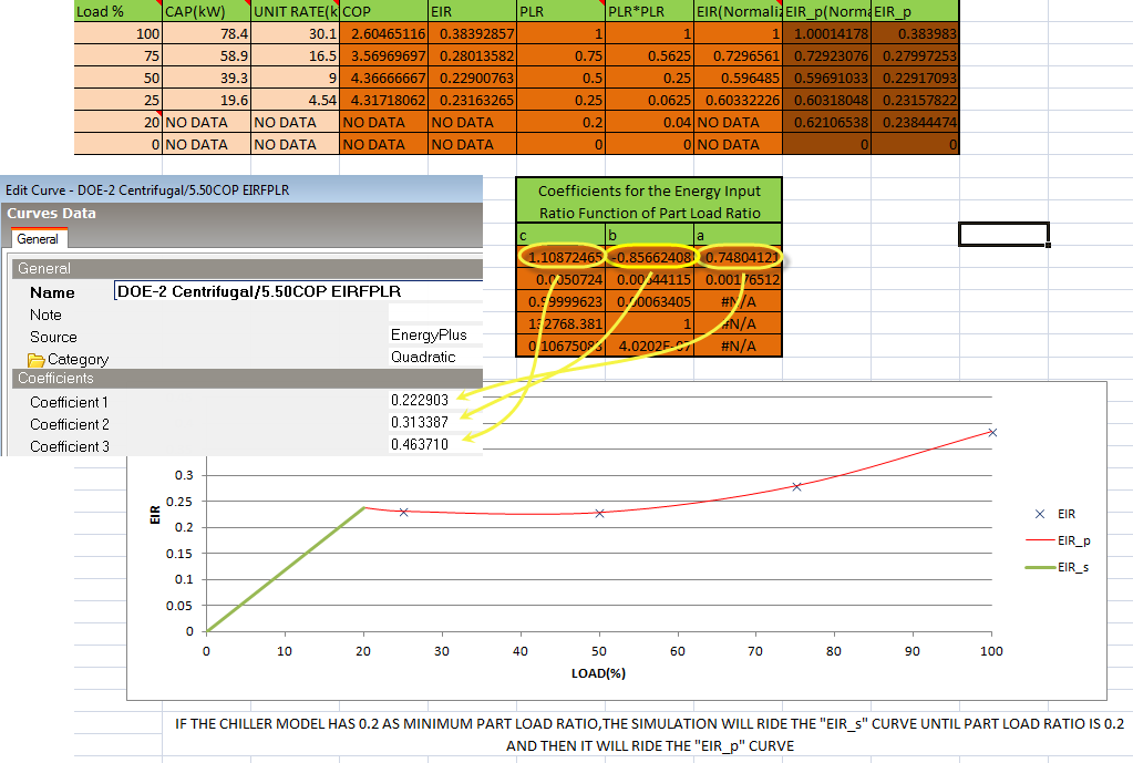
Of course the performance and capacity of a chiller depends on various factors, the most important of these being part load and temperature chilled water and the Chiller EIR provides an accurate representation taking these factors into account. However in some cases you may only have summary manufacturers data. For example you may only have information on the variation of CoP with part load ratio. In this case you can define the EIRPLR curve in the usual way using your summary manufacturer’s data and use constant values for the CAPFT and EIRFT curves which both generate a constant value of 1.0. Because CAPFT and EIRFT are both Bi-quadratic curves you cannot use a constant Linear curve here so you must choose inputs to a special simple Bi-quadratic curve that generates an output of 1 regardless of inputs. To achieve this simply create and select a new Bi-quadratic curve with Coefficient 1 = 1 and all other coefficients = 0 for CAPFT and EIRFT.
This numeric field contains the chiller’s minimum part-load ratio. The expected range is between 0 and 1. Below this part-load ratio, the compressor cycles on and off to meet the cooling load. The Minimum part load ratio must be less than or equal to the Maximum part load ratio. The default value is 0.1.
Note: Setting the Minimum part load ratio to zero for air cooled chillers, will cause the condenser fan to run constantly even at zero load which is likely to lead to high chiller fan consumption. This happens because the condenser fan cannot cycle off even at zero chiller load.
This numeric field contains the chiller’s maximum part-load ratio. This value may exceed 1, but the normal range is between 0 and 1.0. The Maximum part load ratio must be greater than or equal to the Minimum part load ratio. The default value is 1.0.
This numeric field contains the chiller’s optimum part-load ratio. This is the part-load ratio at which the chiller performs at its maximum COP. The optimum part-load ratio must be greater than or equal to the Minimum part load ratio, and less than or equal to the Maximum part load ratio. The default value is 1.0.
This numeric field contains the chiller’s minimum unloading ratio. The expected range is between 0 and 1. The minimum unloading ratio is where the chiller capacity can no longer be reduced by unloading and must be false loaded to meet smaller cooling loads. A typical false loading strategy is hot-gas bypass. The minimum unloading ratio must be greater than or equal to the Minimum part load ratio, and less than or equal to the Maximum part load ratio. The default value is 0.2.
Different chiller types (reciprocating, centrifugal etc) have very different operating characteristics. The point at which they switch off at low load (cycle on and off to meet small loads) will vary between about 0.25 for older reciprocating chillers and 0.1 for modern centrifugal chillers which have much better part-load performance. Sometimes a manufacturer or installer may need to introduce a mechanism to stop the chiller cycling on and off too frequently (frequent cycling causes excessive wear and reduces the equipment life). To stop this happening some of the hot gas from the compressor outlet can be re-injected back into the return side of the compressor so that the compressor inlet senses a higher return gas temperature and is ‘fooled’ into thinking that there is a higher cooling load on the system than there actually is (this basically mimics a higher evaporator leaving temperature) so it needs to work a little harder to meet the load and the load is therefore maintained above the point at which the compressor would normally switch off. This strategy is called false-loading and it is clear that bypassing hot gas from the discharge to the suction side of the compressor results in higher energy consumption so is generally not considered to be an acceptable control strategy and actually contravenes some energy codes (e.g. Part L2 in UK). This strategy is sometimes used to overcome poor design and control problems.
You can avoid false loading in your model by setting the Minimum unloading ratio equal to the Minimum part load ratio, so when the chiller reaches its minimum part-load ratio it just switches off and false-loading cannot occur.
If heat is to be recovered from the water-cooled condenser check this checkbox and ensure that a heat recovery loop is specified and attached to the chiller.
Note: Use the Add Chiller heat recovery loop command at HVAC system level to create a DHW loop that can be connected to a water-cooled chiller with heat recovery. This allows the waste heat from the chiller to be used to heat up a water tank which can be used to provide hot water for DHW, zone heaters or any other heating applications.
Enter the design heat recovery water flow rate (in m3/s or gal/min). This field is autosizable. When autosizing, the flow rate is simply the product of the design condenser flow rate and the condenser heat recovery relative capacity fraction set in the field below.
This field is used to describe the physical size of the heat recovery portion of a split bundle condenser section. This fraction describes the relative capacity of the heat recovery bundle of a split condenser compared to the nominal, full load heat rejection rate of the chiller. This fraction will be applied to the full heat rejection when operating at nominal capacity and nominal COP to model a capacity limit for the heat rejection. The default capacity fraction is 1.
Check this checkbox if you would like to define an upper limit for the return fluid temperatures entering the chiller at the heat recovery inlet node (see below)
If the Inlet high temperature limit checkbox is checked then you must select the schedule to be used to control heat recovery operation of the chiller. The schedule should contain temperature values, in °C, that describe an upper limit for the return fluid temperatures entering the chiller at the heat recovery inlet node. If the fluid temperature is too high, then the heat recovery will not operate. This is useful to restrict the chiller lift from becoming too high and to avoid overheating the hot water loop.