
This modelling guide summarises the main steps involved in setting up generators as part of a co-generation (electricity + heat generation) system. You can read more details about the individual components on other pages.
1. Add and configure generators in a detailed HVAC model, typically in hot water or DHW supply sub-loops or condenser demand sub loops (see screenshots below).
Note: To model a generator that works alongside a boiler as a backup heating source you should use the series configuration where the boiler is placed on the supply sub-loop outlet branch instead of the usual branch that connects between the splitter and the mixer (see screenshot below). The parallel arrangement does not work as expected in EnergyPlus v8.9 and is not recommended.
Generator in a HW loop with a backup boiler
The arrangement of A DHW loop hot water tank heated by a hot water loop with generator(s) integrated and acting as a heating source is another tried and tested system (see below). The hot water tank has an internal built-in gas (or electric) boiler that provides backup heating to top up the building heat demand if the heat delivered from the generator(s) is not sufficient to meet the heating load.
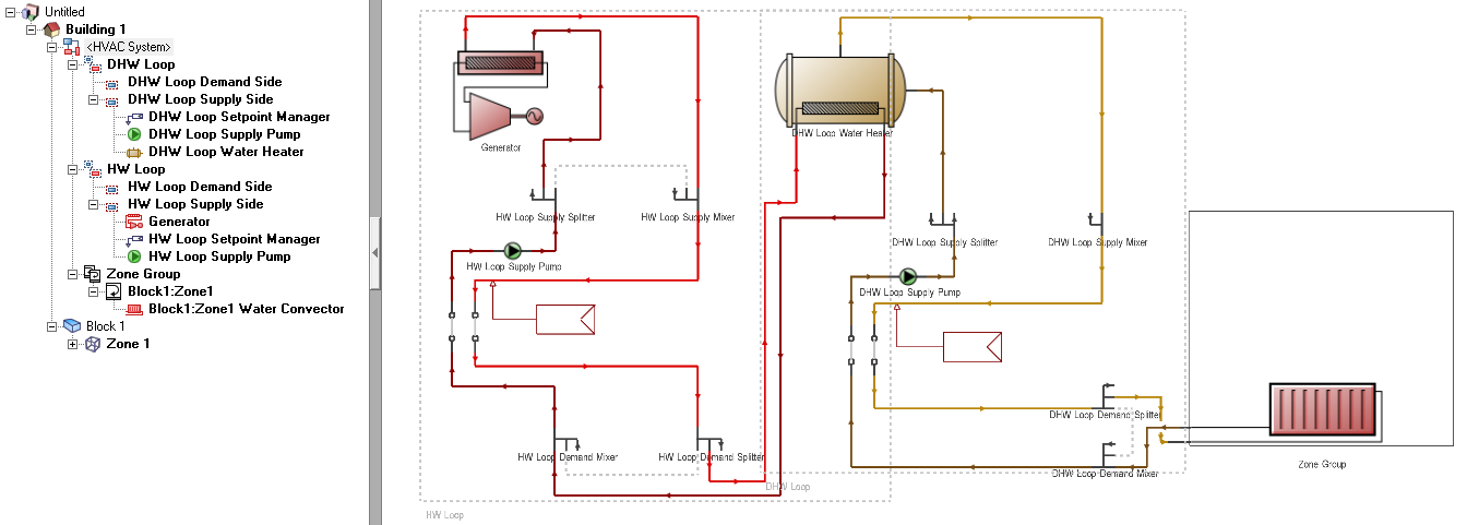
Generator acts as a heating source to a hot water tank
Tip: Both of the systems described above can be loaded from DesignBuilder Detailed HVAC templates.
An alternative arrangement is where the generator is placed on the demand sub-loop of a condenser loop and the condenser loop uses a fluid cooler for heat rejection. The recovered heat from the generator is supplied to a hot water loop through a fluid-to-fluid heat exchanger (HX) that is in parallel to a boiler. The HX is set at higher priority than boiler in hot water loop equipment operation scheme.

Note: In the above case, the operation scheme for the electric load centre that contains this generator should be set to 1-Base load to allow the generator to operate and for waste heat to be recovered. The requirement to use the 1-Base load scheme applies because the generator located in the demand sub-loop cannot be included in the plant equipment definition, and therefore cannot obtain the heat demand signal from the heating zone. If the heat exchanger reaches operating conditions, i.e., there is available heat that can be transferred from the demand side to the supply side, and also the heating zone has a heat demand, it will operate.
2. After adding generators into HVAC loops, make sure to enable/include them by checking the corresponding checkbox on the Plant equipment operation tab of the plant loop dialog (screenshot below).

Enable generators in plant equipment operation equipment list
3. The generator type, one of 1-Internal combustion engine or 2-Micro turbine, can be selected from the generator dialog (screenshot below) along with the other generator attributes.

Generator type selection
4. Ensure that the Include electric load centres checkbox is checked at building level (on Generation tab) and enter the number of electric load centres for the model, which must contain all the HVAC generators modelled in the HVAC system. The selection can be done on the Generator List tab on the Electric load centre dialog when one of the alternating current Electrical buss type is selected (screenshot below). Both type and number of generators defined in electric load centres should match those modelled in the detailed HVAC system, and there should not be any duplicated entries. In other words each generator defined in the Detailed HVAC system must be selected exactly once on a load centre generator list.

Define generators list on electric load centres
5. If the generators list defined in electric load centres does not match the number and type of generators modelled in the Detailed HVAC system, then the following error message will be displayed when attempting to run a simulation:

Error message indicating the mismatched generators list
6. Operation schemes are selected on the General tab of the electric load centre dialog. The commonly used operation schemes for generators are: 1-Base load, 5-Follow thermal or 6-Follow thermal limit electrical. The 1-base load scheme operates the generators at their rated electric power output whenever the generator is scheduled on, and treats the produced thermal energy as ‘by-product’. In contrast, the 5-Follow thermal and 6-Follow thermal limit electrical schemes operate the generators to meet building’s thermal demand, and treat the produced electric energy as ‘by-product’.

Electric load centre operation schemes
7. After the simulation, the fuel consumption breakdown and electricity generation can be displayed at building level (screenshot below).

Fuel consumption and electricity generation reporting